This post will go through a mesh inspection example that highlights the importance of CAD clean up and its effects in the meshing operation.
A very important pre-processing step of a simulation is CAD preparation. Optimally, details that have a negligible effect in the simulation results should be removed from the CAD model.
During the simulation process, an algorithm uses the CAD model to generate a mesh, which is later on used in the simulation itself.
When the CAD model has a huge amount of details/topology defects, the meshing tool may require many additional cells to capture the small details. This typically leads to finer meshes and worse quality cells.
All in all, a dirty CAD model may cause:
- Finer meshes: more runtime and computational resources
- Poor mesh quality: instabilities during the simulation, divergence, more runtime to achieve convergence
- Failure in the meshing and simulation operations
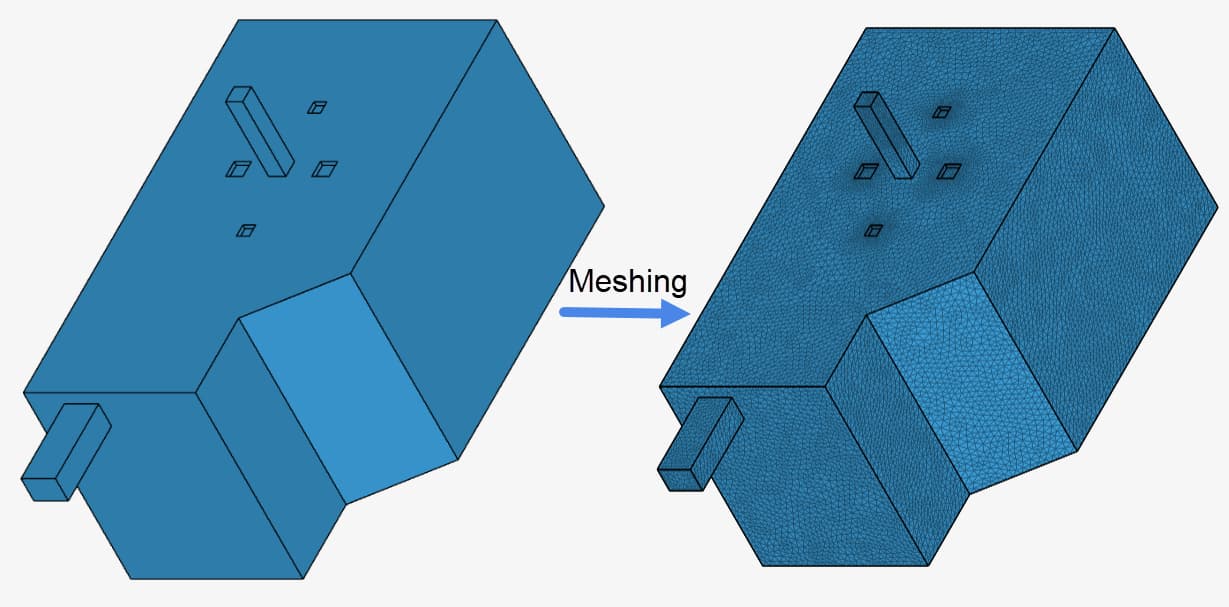
The most common issues in CAD models are very small faces and very small gaps. For illustration purposes, here is a project containing two versions of a room geometry and their respective meshes (clean mesh and dirty mesh)
Both CAD versions are almost identical, however 4 issues were introduced to the “dirty” version: 3 small faces and 1 small gap. Immediately, from selecting the CAD models and expanding Geometry info, we can see a huge difference between the smallest surface from the models:

The area of the smallest face in the dirty model is 5 orders of magnitude smaller than the smallest face in the cleaner model. Let’s see how much these CAD issues will impact the meshing operation.
For demonstration and comparison purposes, both meshes use default settings. First, a quick comparison of the mesh quality metrics. Here are the metrics from the dirty CAD:
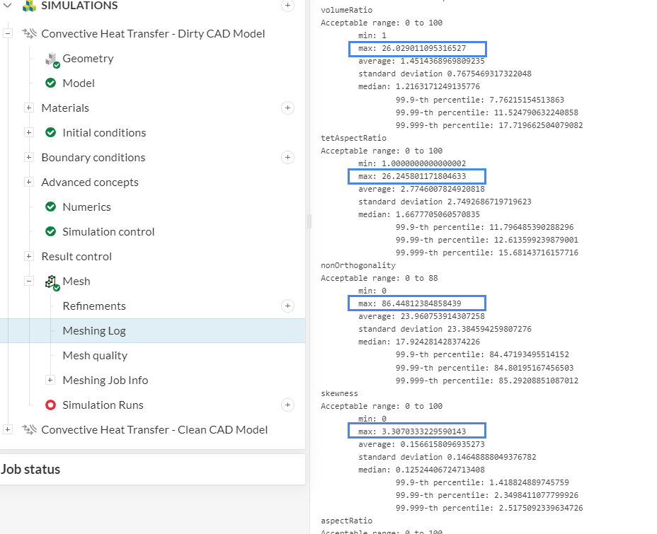
Metrics-wise, it is always interesting to have a look at the “maximum” values, since a handful of very poor cells may potentially cause instabilities. Although these parameters are within the acceptable range, the non-orthogonality values in particular could be further improved.
Having a look at the metrics from the clean mesh:
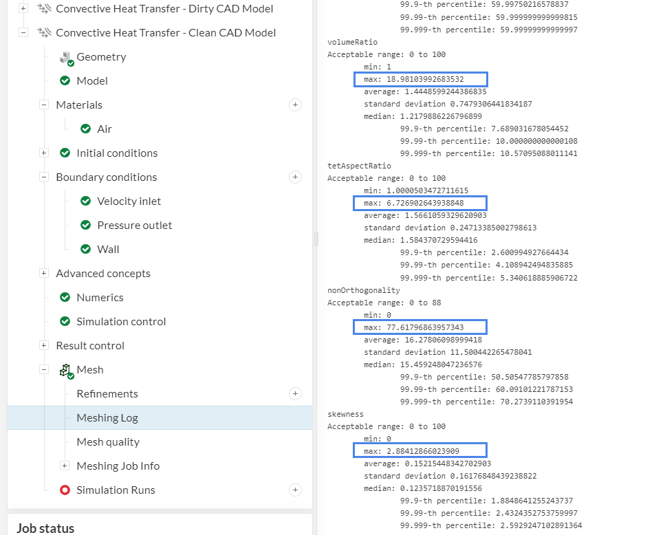
All of the mesh quality parameters are vastly better, especially the non-orthogonality , which dropped from 86 to 77.
The standard meshing tool is a bottom-up algorithm, meaning that first it meshes the surfaces, and only later it will mesh the volume. This means that the standard tool excels at capturing surface details with precision - and this includes potential small faces or detailed topology that you might have.
As a result of this behavior, from a visual mesh inspection, you can easily pinpoint regions with potential CAD issues. Regions with a much larger mesh density and/or heavily asymmetric parts are good indicators that there might be something in the CAD model.
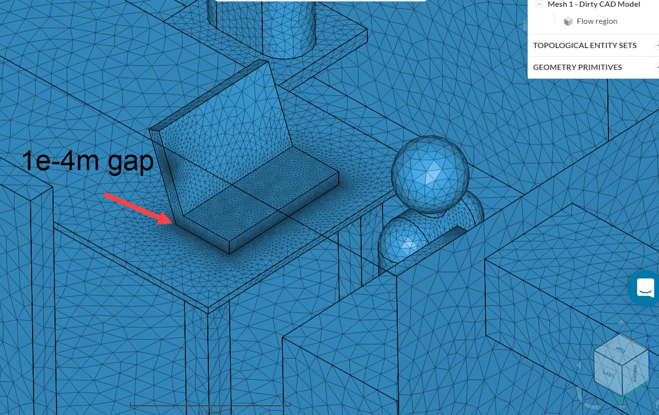
Having a look at the resulting dirty mesh, it’s possible to find regions to be explored:
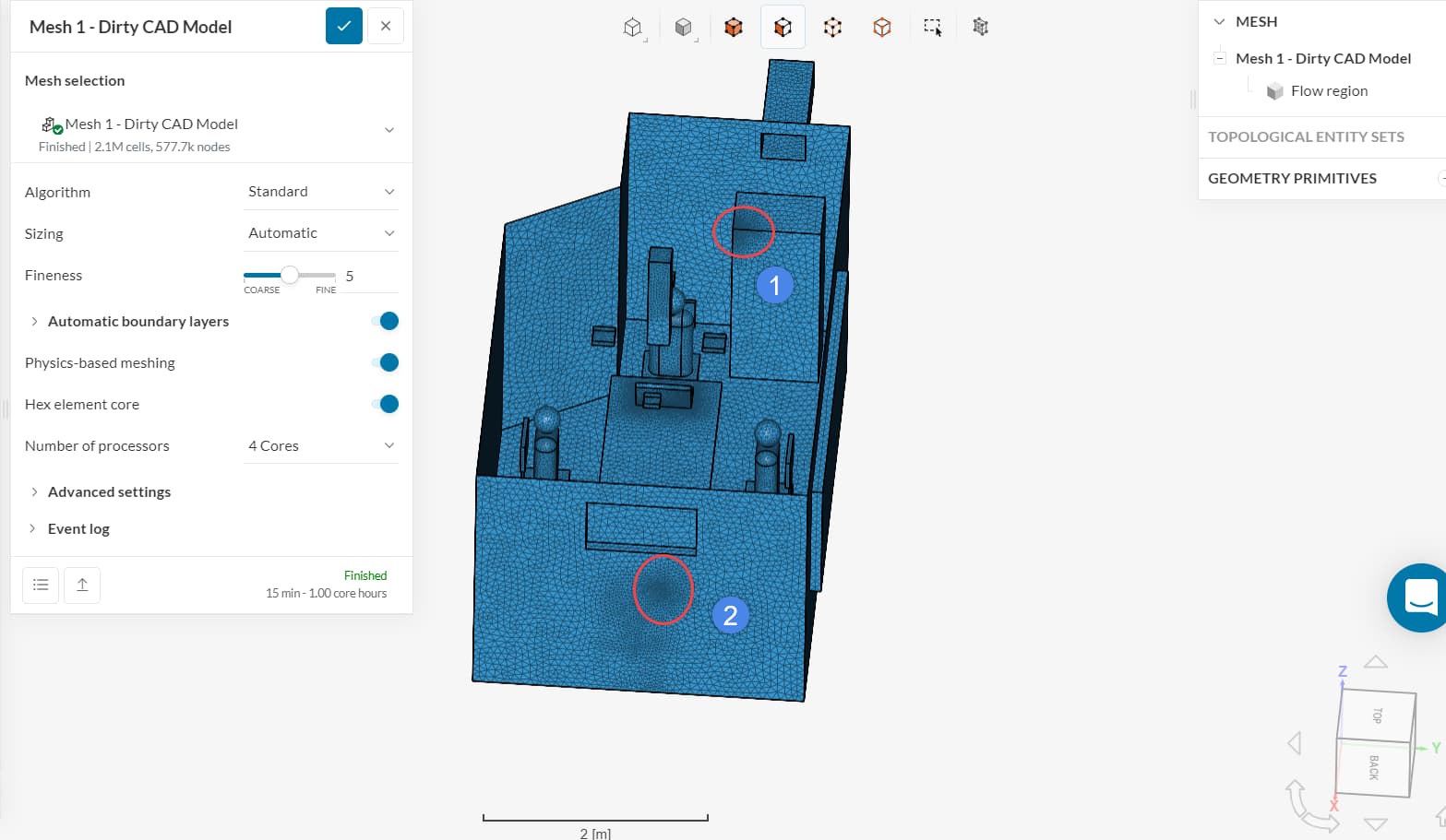
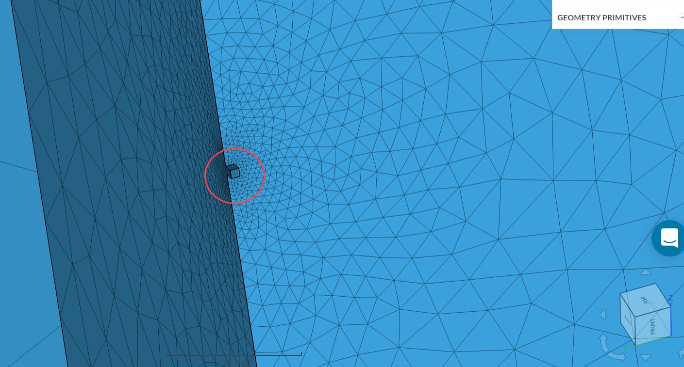
Region number 1, in the cabinet, is clearly asymmetric when compared to the other cabinet corners. Region 2 shows a slightly finer region around the wall that could be worth inspecting. If we zoom up in region 1, we will find the smallest face in the CAD model, with 5e-8m² of area:
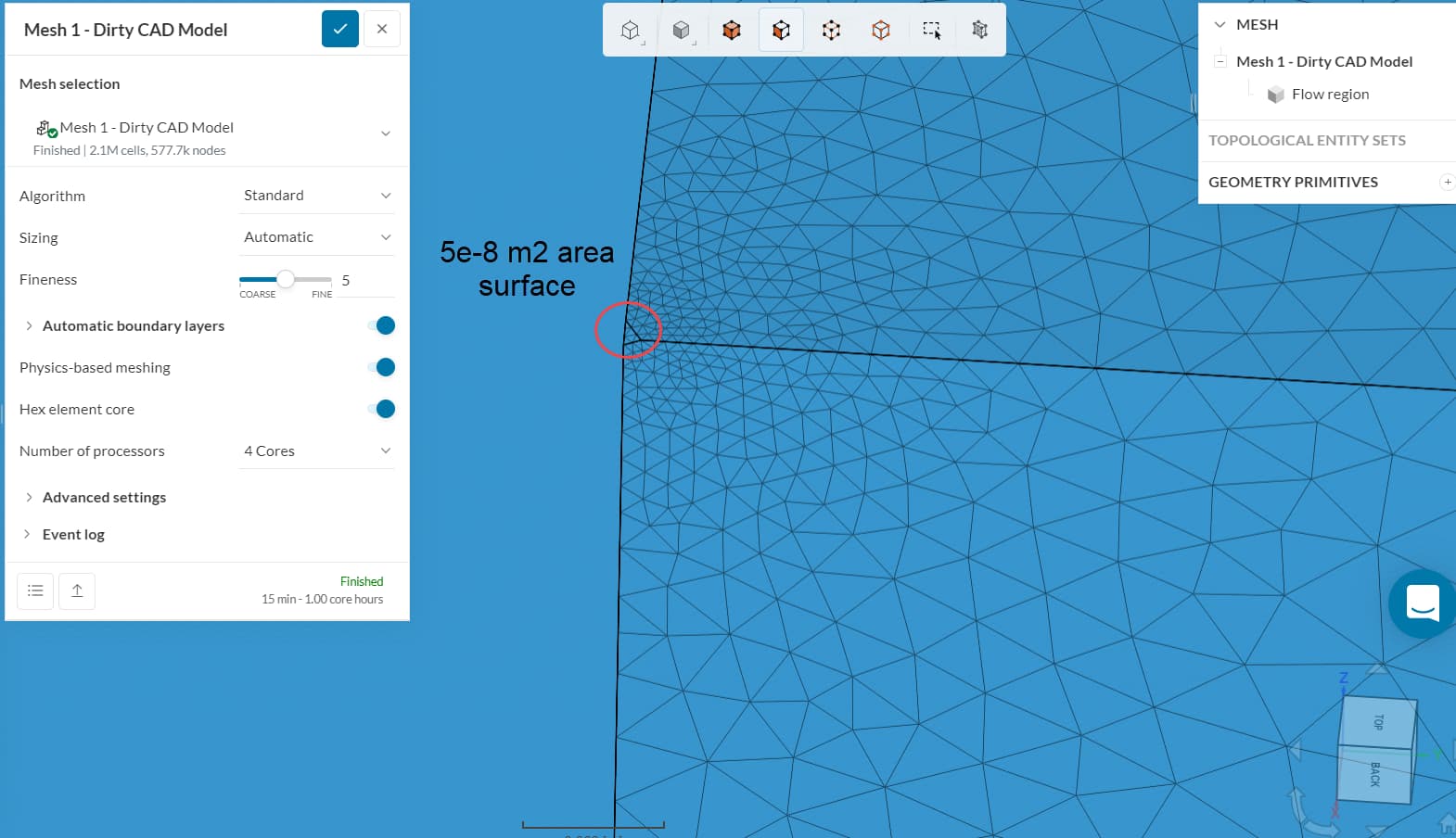
It is responsible for the huge mesh density observed in one of the corners of the cabinet. Having a look at a different angle, we can pinpoint more regions of interest:
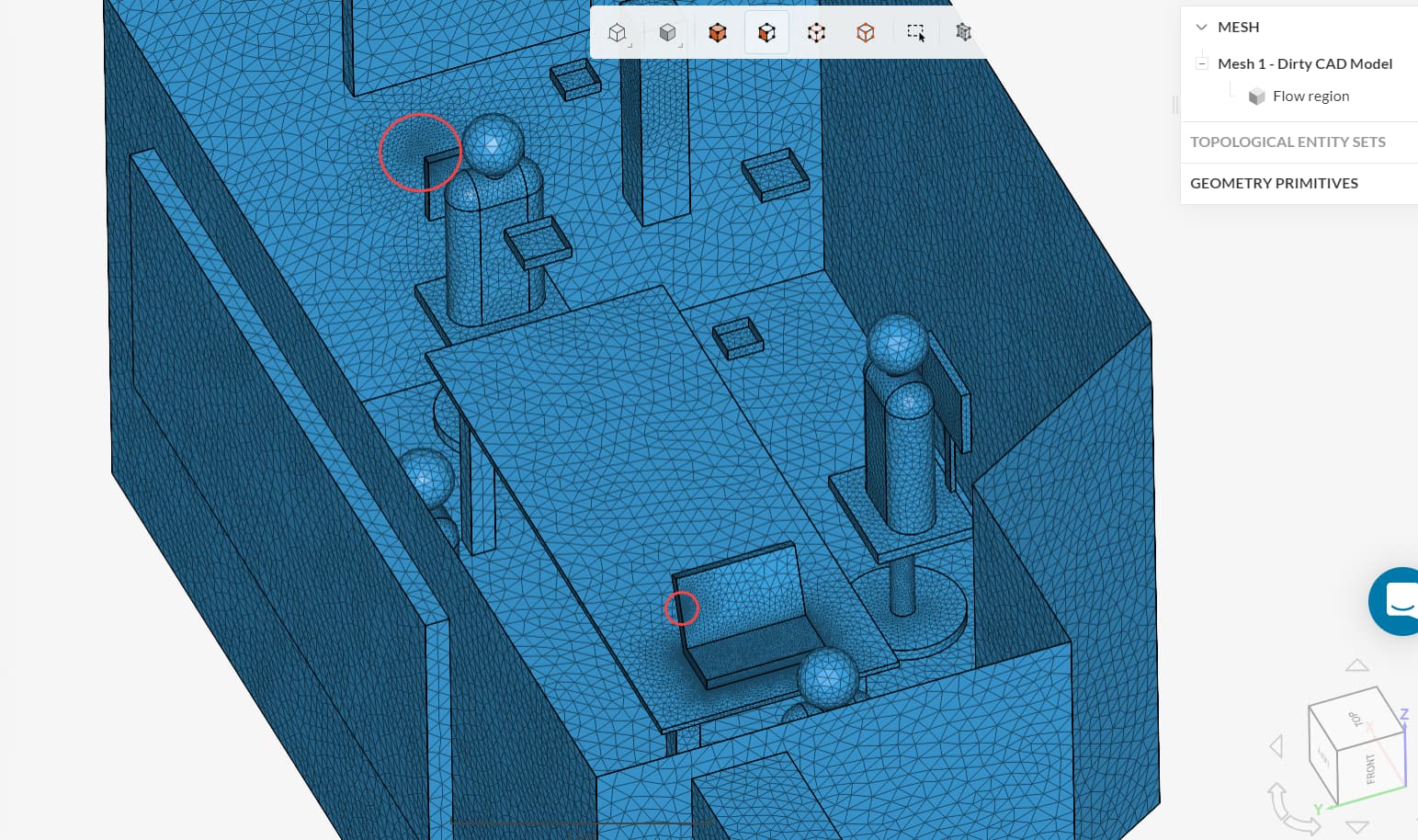
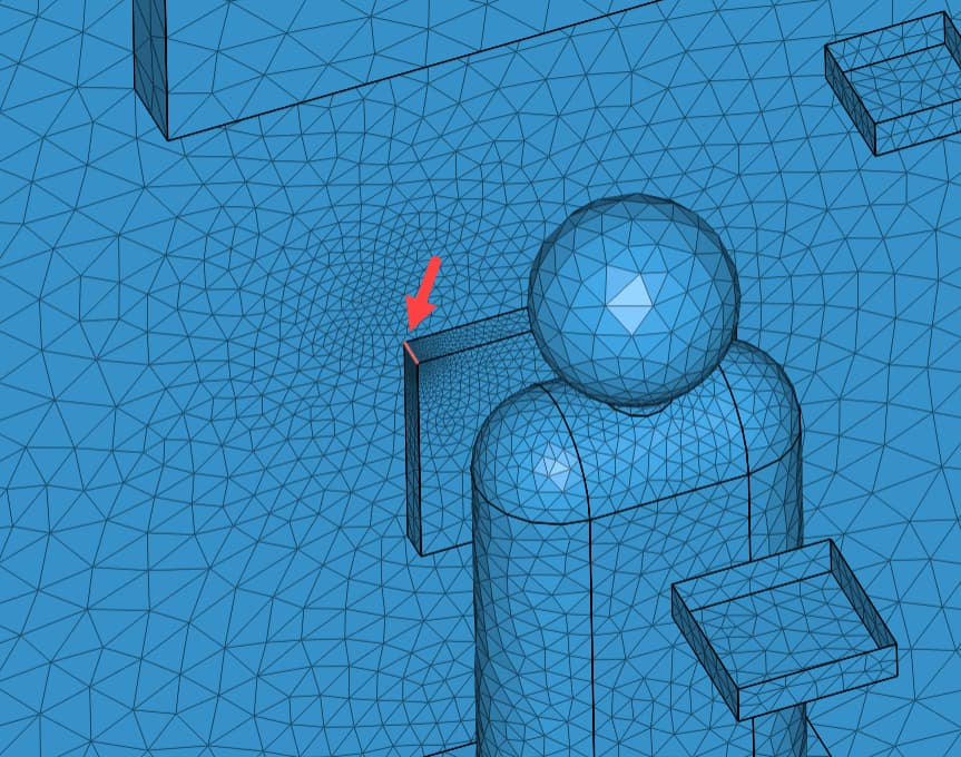
The one on the laptop is again caused by a small face:
And the missing small face is on the chair. The effect of this small face is still observed on the wall behind the chair.
The missing issue is a small gap of 1e-4 meters between the laptop and the table. You can see that there’s a larger cell density all around the laptop:
And ultimately, a difference is also observed in the cell count and resource usage for the meshing operation:
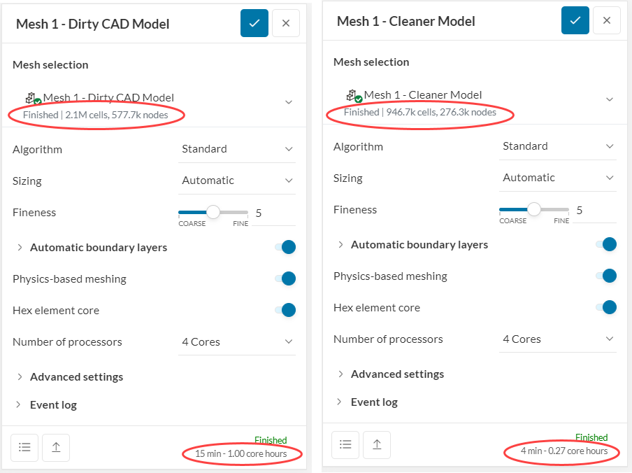
As a summary, the small CAD issues that were introduced in the model caused the mesh quality to drop, took about 4x as many core hours and 2x as many cells to mesh, and do not add any benefit when it comes to simulation results.
Although this application is generic, the same ideas can be used for other simulations: removing small details of the CAD model can improve the simulation workflow greatly. Operations such as Delete face and Gap in CAD mode are helpful to achieve this goal.