I have been trying to model SPR’s in a structure for a dynamic analysis. Since these are small, this increases the run time due to the size of the elements. Is there another way of modelling this without reducing the element size and still able to run the model comfortably?
I would normally suggest to merge the SPR’s and the remaining of the structure in CAD, but in your case the SPR’s and the rest of the structure consist of different materials, so that would not work.
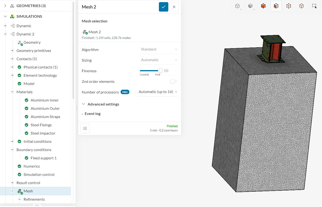
With that being said, try to optimize the mesh settings - I noticed that most of your meshes have a large value for the global fineness:
The global fineness, as the name suggests, is applied to the entire structure. This will generate extra cells in the regions of interest, and also in the regions which don’t require a fine discretization.
Therefore, I’d recommend reducing the fineness back to default (5) and applying local element size refinements to the regions of interest (e.g. the bolts).
I need some help with this run. Albeit, the simulation worked, elements have penetrated through each other. Also the outcome is unrealistic. Please can you take a look at the following link and let me know your thoughts on this issue.
The actual simulation run is entitled: “Dynamic 3 - No Holes, No SPRs”.
Would appreciate your help with this. I have tried several things: Refining the mesh, using the default parameters, reducing the time step. checking all elements to ensure good element quality. The other issue is that I have had to reduce the run time resulting in high core hour usage.
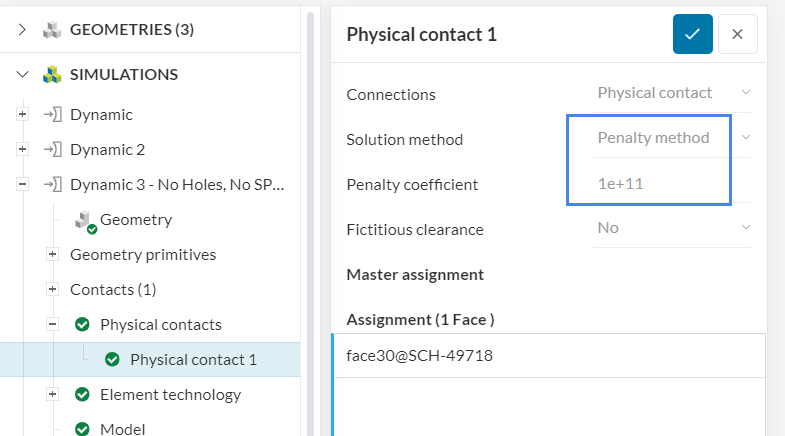
Thanks for looking into this issue for me. I have tried different penalty coefficient based on the suggestions made in the link which you sent me. No solution. Please see the link below:
I have changed from Implicit to Explicit integration with no success. Just wondering what I can do next to get the simulation to work.
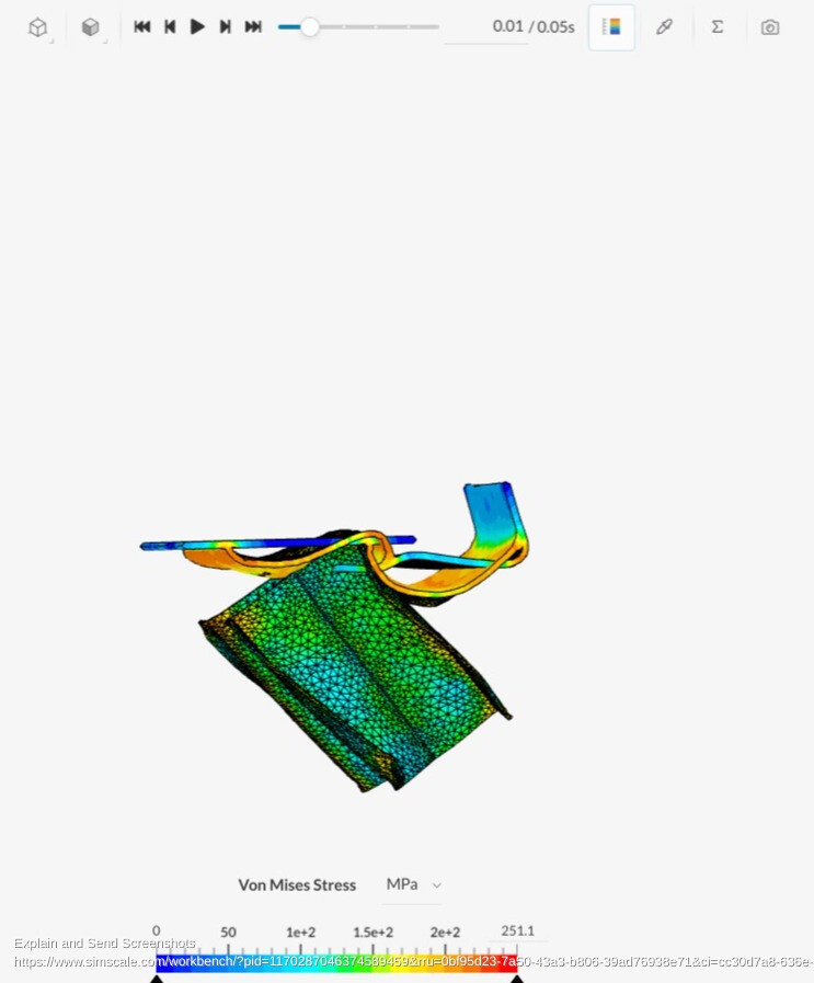
It looks to me like your physical contact is working just fine. The aluminum channel is being crushed by the steel object. In the images from the first two saved steps you can see how the channel is being twisted around and inverted.
The issue you do have is that the two aluminum parts are not staying together. You defined there contact using a Sliding Contact. However, a Sliding Contact is ONLY valid for linear analysis with small relative displacements. You will need to look at a Bonded Contact or a Physical Contact or a combination of the two.
Please let us know if this helps.
Good Luck,
Christopher