A boundary layer fan is basically an inverted Tesla turbine, where instead of converting a moving air stream into rotational motion, it turns rotational motion into moving air. Basically what a bladed fan does, only instead of relying on blade angle to push air it uses the boundary layer to drag it along.
So spin a disc in a fluid and the centrifugal forces on the boundary layer will drag the fluid outward. And it really does work that easily.
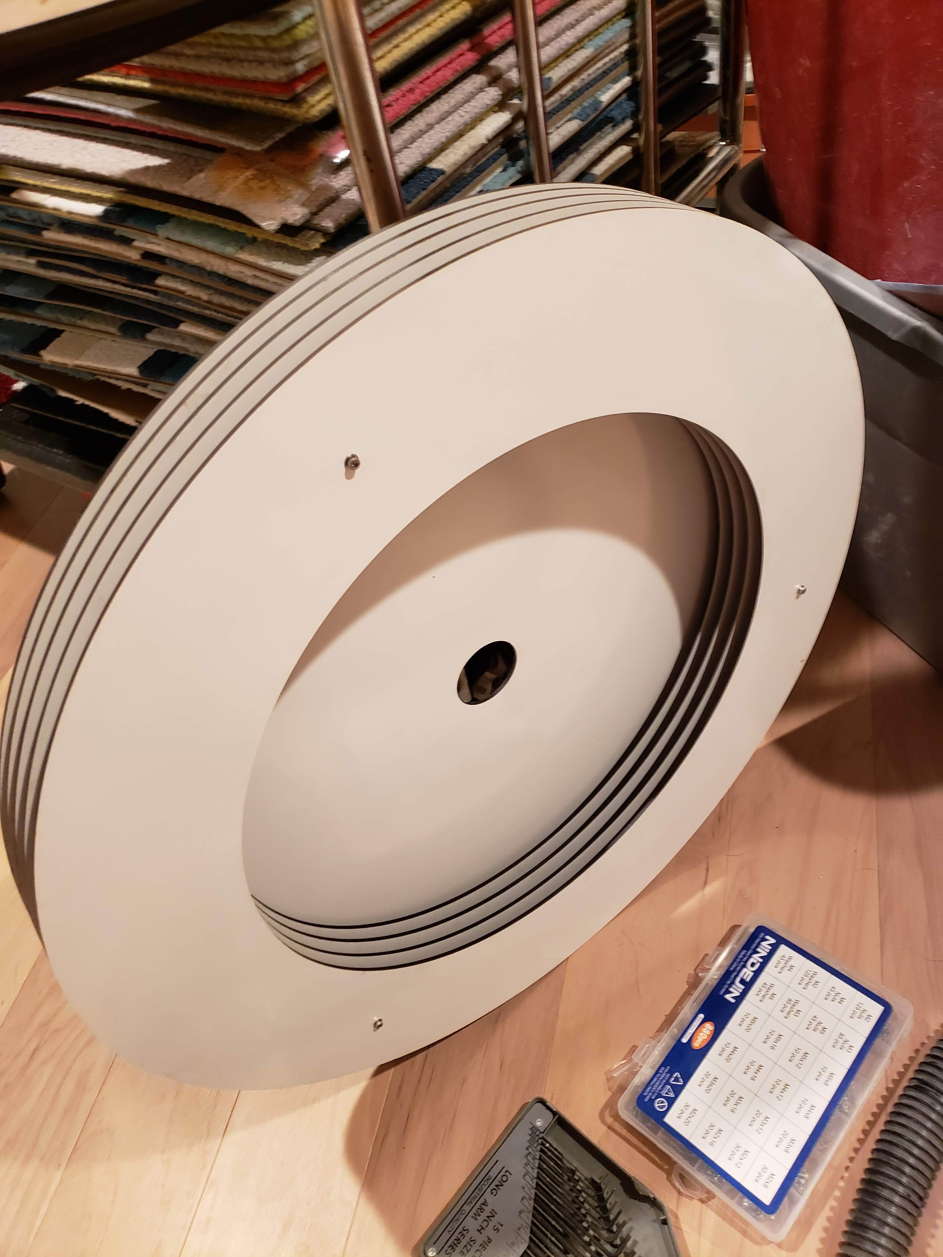
For some highly specific purposes, I needed a small boundary layer fan so I made my own:
How to model this, though? I have a simple parts CAD in Onshape (it’s just a series of flat platters), but for a first-timer it’s not clear how to turn the platters into a simulation. I’d love to experiment on my own and figure this out, but the computational costs of an error are very high and the iteration time is very low so I thought I’d ask here first. Here’s what I could use some help with:
Is MRF or AMI appropriate here?
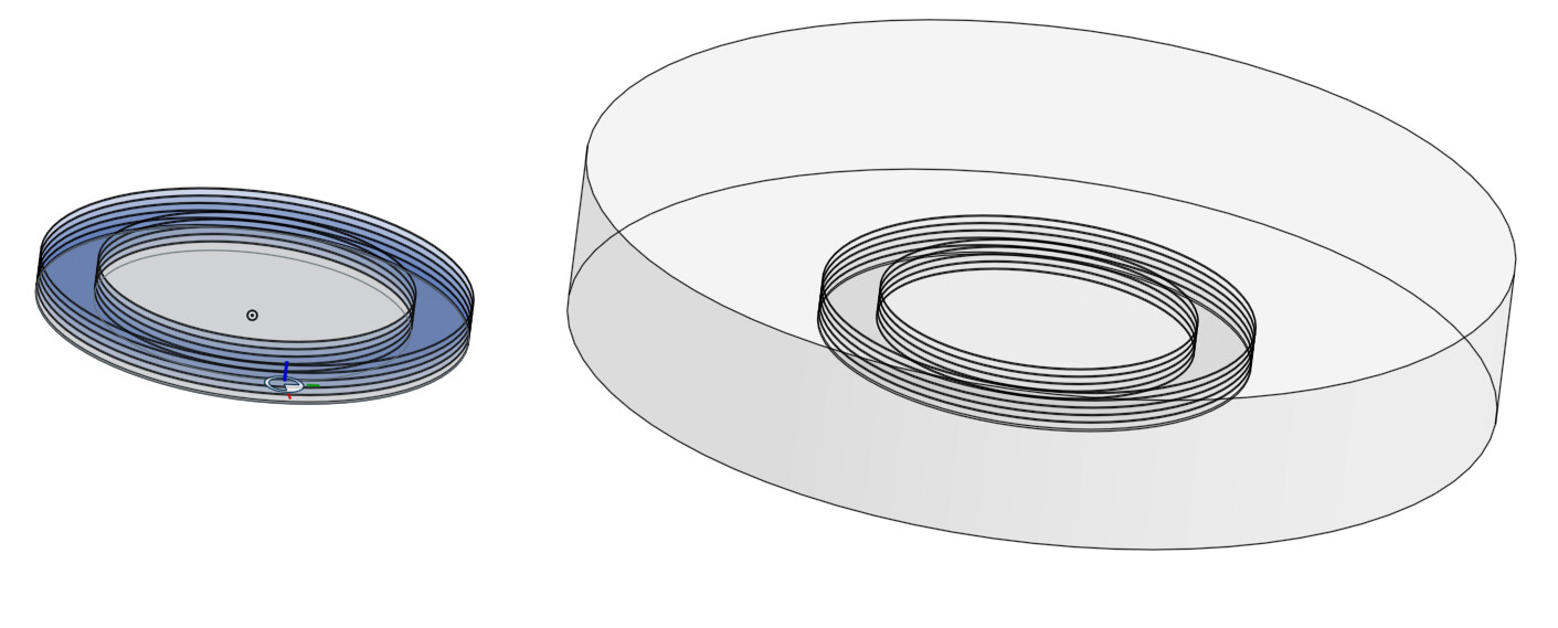
What, precisely, is the CAD model I should use? Some of the examples I’ve found seem to show importing a block of the negative space around the fan blades. AFAICT they then use MRF to spin the negative block. So should I import my discs, or should I make an enveloping cylinder and take the boolean of it using the discs as the subtraction tool?
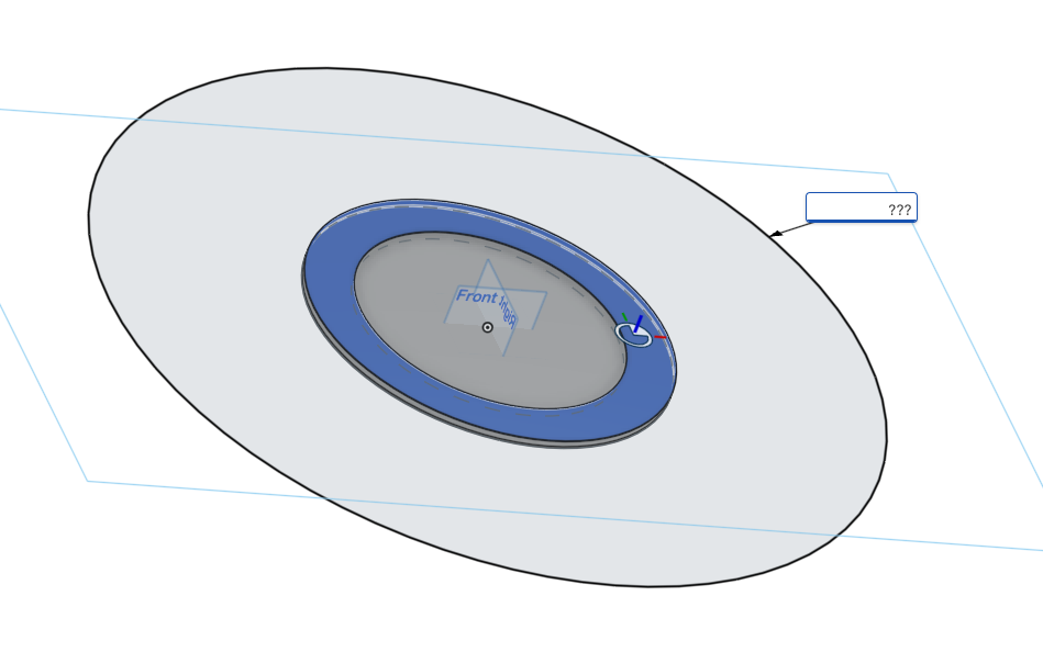
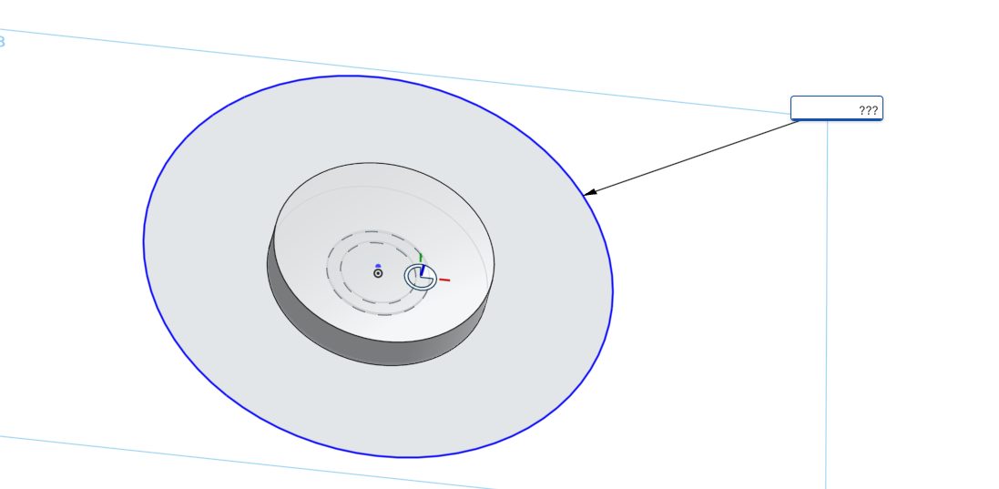
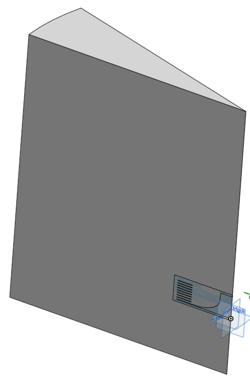
I.e., in the below picture should I import the solid positive model on the right or the empty negative model on the left?
There’s a well defined inlet, but the outlet is the faces of the cylinders made by the openings between discs. How do I define these outlets?
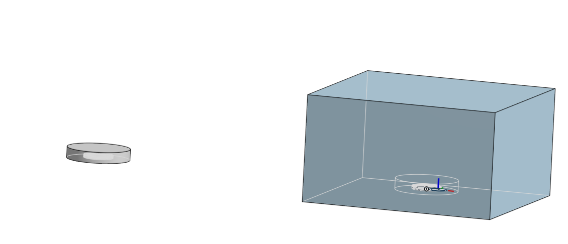
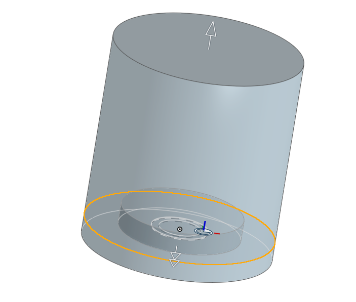
Do I need to create a room if all I’m interested in is simulating the effects of disc size and spacing? I.e., do in the below image do I want to simulate the one part on the left or the two parts (fan + box) on the right?
I would start to setup most simplistic incompressible simulation possible:
Create just two disks (with holes inside).
Create an enclosure (it can be even a cylindrical one, you will handle only two faces.
Create boolean volume of removing your disks from that enclosure (it will be your simulation domain).
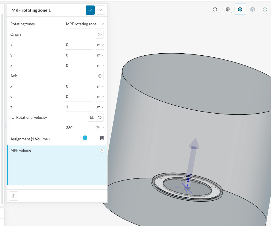
Add MRF zone (a cylinder slightly bigger surrounding your two disks).
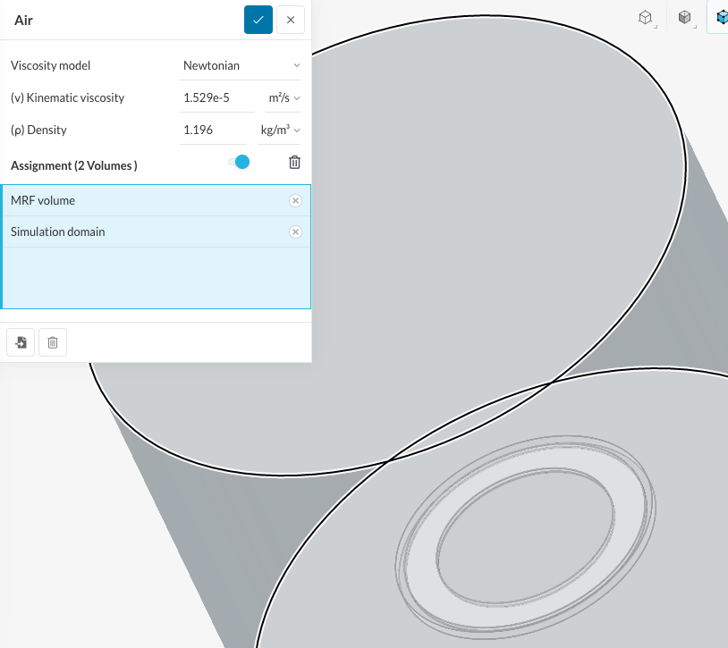
Import the simulation domain and MRF solids to SimScale (from OnShape): just two volumes.
Setup incompressible simulation (it will be k-omega STT).
Mesh it with standard mesh, but add refinement around your disks and refine disk surfaces. You should have at least 3 mesh cells in space between disks, but better is more, which is making mesh quickly bigger.
Your simulation domain will not have any inlet / outlet: just boundary conditions set to “slip”. Air will be circulating (I expect) in that volume thanks to Tesla disks.
Set ‘Foame initialization’ to yes in simulation preparation.
Initiate rotation with MRF: mind that you should not go over 0.3 of Mach (linear flow).
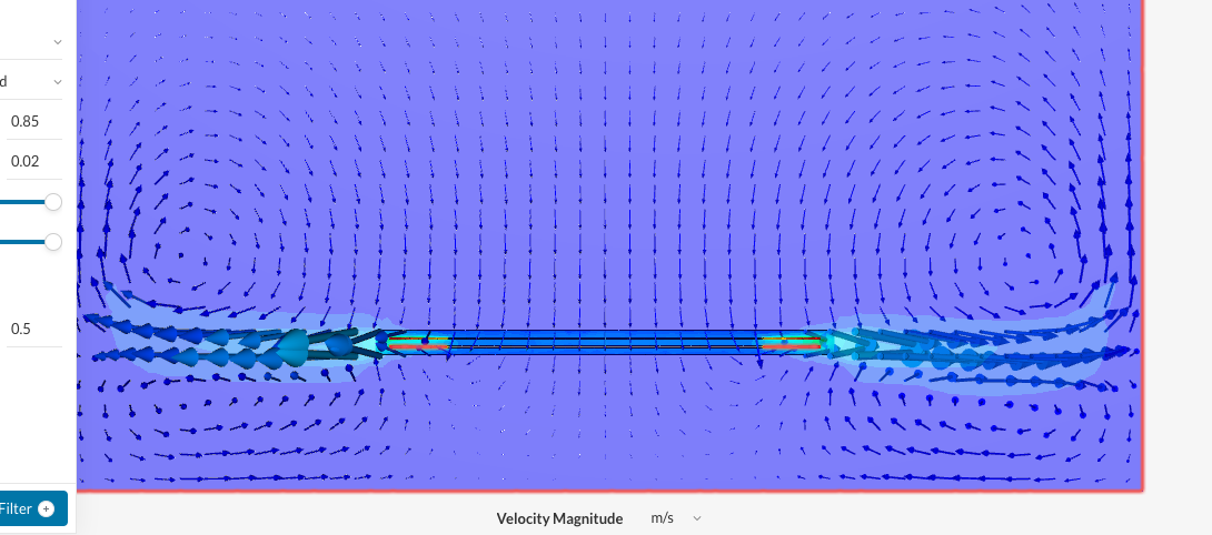
Observe flow, put probes, experiment with that simple setup first.
1 . “You should have at least 3 mesh cells in space between disks, but better is more, which is making mesh quickly bigger.” ← This cannot be determined until after the mesh is completed, correct?
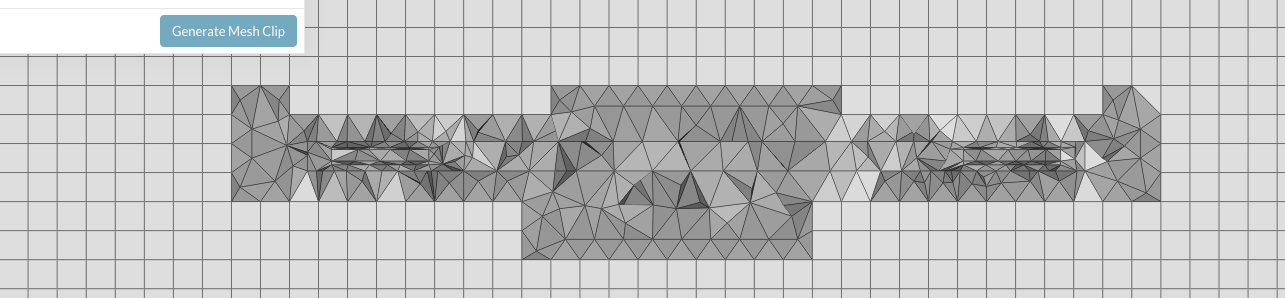
It’s a little hard to tell because I can’t find a section view tool, but it seems to me that I don’t have 3 mesh cells between the discs:
To which faces are the Wall–>Slip boundary conditions applied to? Only the Simulation domain’s cylinder wall, or the top and bottom of the Simulation domain as well?
Do not put the plate on your disk: Disks with a hole will take air from both sides. (Perhaps later on).
Done. I don’t fully understand why I would want to take air from both sides since the fan allows air in from only one side, but I’ll work on that later.
Make your disks axis in the center of that simulation domain (on drawings it is now displaced).
I think what you’re seeing is a drawing artifact. It’s a Mate point which got imported from a derived model and I can’t hide it or delete it. In any case, the object itself is centered on the origin, as can be seen from the MRF tool.
Make your domain only 2-3 times wider compared to disks diameter.
Make your domain the same high as the domain diameter (can be smaller).
Make MRF cylinder only 3-6 % bigger than your disks.
Do you think it could be that there’s no boundary conditions on the MRF volume? Perhaps there should be no-slip wall conditions on the blade surfaces?
Out of curiosity, is there a way to pause a simulation a few iterations in so that this kind of mishap can be caught early? It seems a shame to waste the resources and time when it must have been apparent early on that the problem was poorly set up. If I could run for a few seconds I could probably figure this out by just poking at things until I get to the “aha!” moment.
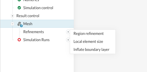
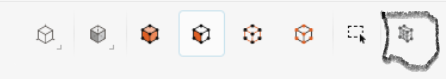
Tool to see cross section…
Thanks for the pointer toward the Mesh Clip button. I had seen the button’s tooltip, but the phrase “Mesh clip” was unfamiliar to me and so I didn’t think much of it.
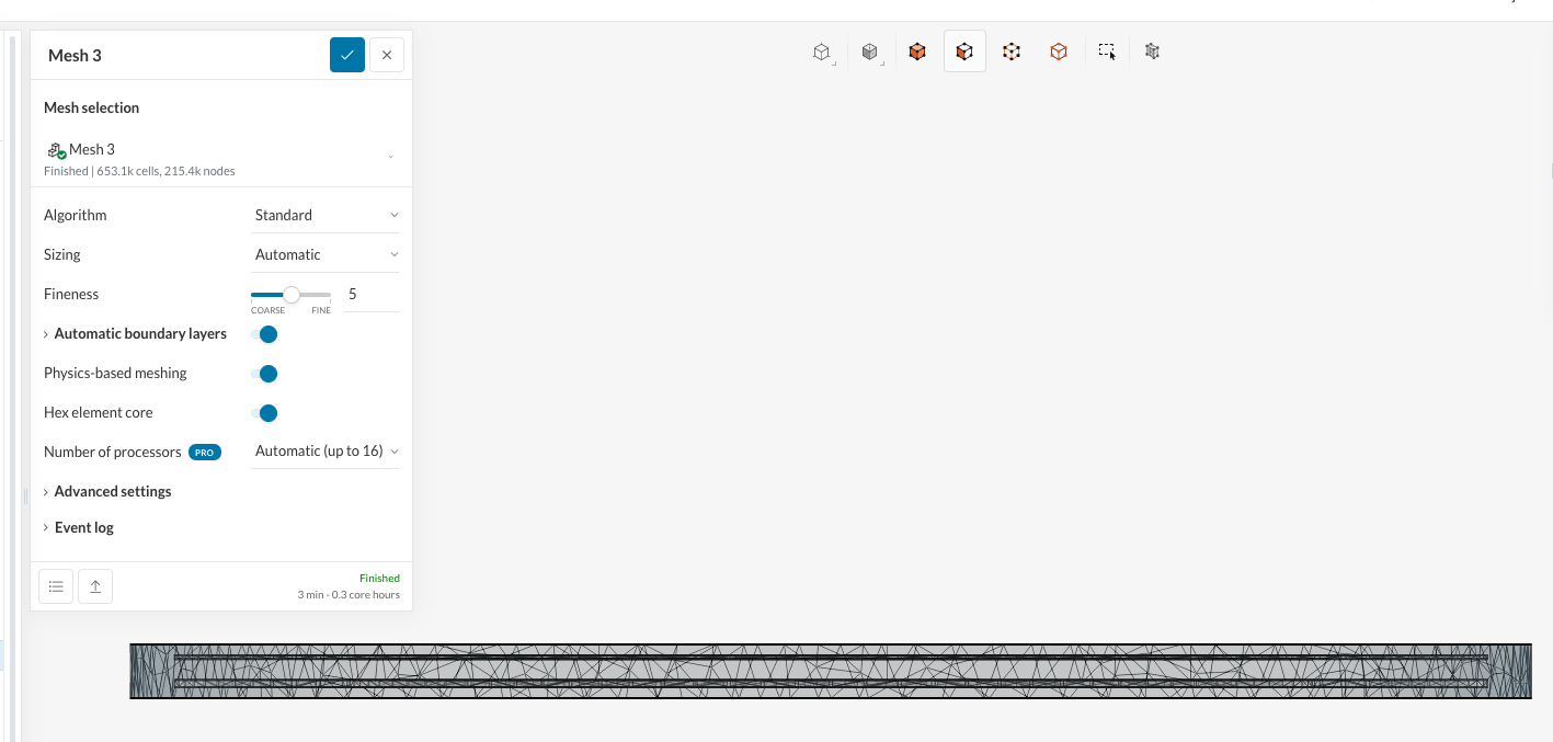
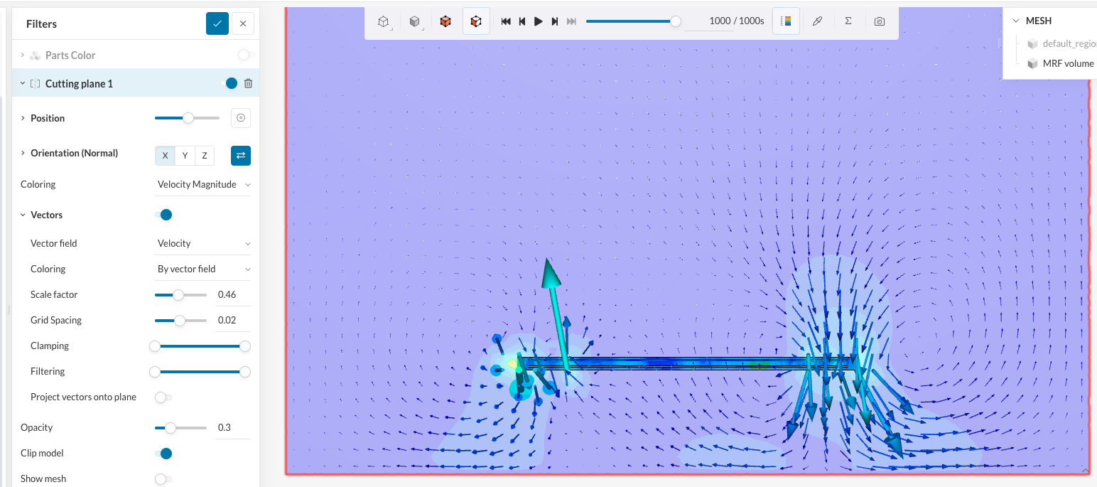
Here’s the midplane taken with the normal vector <0,1,0>. Is it normal that there’s asymmetry in the mesh or is that a bit of a red flag?
Good concern: those seconds are really ‘steps’, not linked to physical time. Set 200 steps, for instance first. You can see the results and discard simulation or press ‘continue arrow’. That way you manage your CPU core-hours budget.
Mesh refinement should be done by adding additional volumes (cylinders), inside simulation setup.
Walls of you device should be no-slip, in any case. This is the wall effect (viscosity) which will cause the air to stick to the surface.
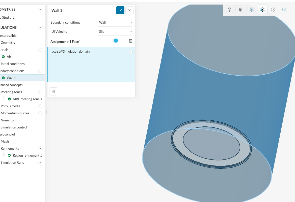
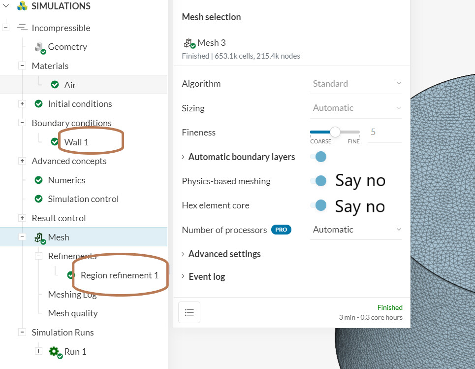
Wall 1 should be set to all simulation domain walls
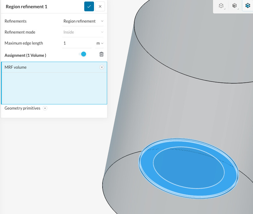
Region refinement (in your case is only for MRF) should be better ( x 2). Set correct value to ‘Maximum edge length’. Not 1 m, please.
Disks surface should be refined to much higher level: that way space between disks will be filled by fine mesh cells).
One more think: Set, in simulation control, ‘write interval’ to observe evolution of simulation graphically, later on.
Tet aspect ratio (from mesh log) after that should be checked: it should not be bigger that ~80 - 100. Now it is still low, which can be used for quick checks first, of course.
Thanks. I went back through and realized I had inverted your directions on the MRF vs. the Simulation Domain. I had subtracted the fan shape from the MRF and had left the simulation volume as a pure cylinder.
I fixed my CAD, yielding:
An MRF which is a solid cylinder 3-6% larger in diameter, and 3-6% taller in height than the fan.
A Simulation Domain which is a solid cylinder 2-3 times larger in diameter; 2-3 times taller in height than the fan; and has a void where the fan elements are.
In addition, I set all Simulation Domain faces to Wall–>non-slip, with the exception of its outer cylinder wall and top/bottom faces, which were set to Wall->slip.
Lastly, I created a cartesian volume (cylinder) which was approximately the same size as the MRF (but a little larger) and set this as the target of the Region refinement.
I regenerated the mesh and this time I saw three cells between the blades. Moreover, the mesh is nicely symmetric. That’s very promising!
I reran the simulation now for 200s (understanding that those are in fact iterations), saving the output every 200s (so I will have one saved point).
Our prior messages were sent at the same time so I didn’t have a chance to implement your new suggestions. Do you still recommend I follow them? If so:
Wall 1 should be set to all simulation domain walls
So you’re saying that I should not have a Wall1 which is slip for all outer dimensions and a Wall 2 which is non-slip for the fan surfaces?
Region refinement (in your case is only for MRF) should be better ( x 2). Set correct value to ‘Maximum edge length’. Not 1 m, please.
Do I need to set this to 0.5m if the results were acceptable? If so, how do you arrive at 0.5m, is that a normally correct value for objects which are in the 10-100cm range?
Disks surface should be refined to much higher level: that way space between disks will be filled by fine mesh cells).
Tet aspect ratio (from mesh log) after that should be checked: it should not be bigger that ~80 - 100. Now it is still low, which can be used for quick checks first, of course.
My new Tet aspect ratio is
tetAspectRatio
min: 1.0000503472711673
max: 8.485397581794299
average: 1.5623686017766634
standard deviation 0.319056615082282
what is the “~80-100” ratio referring to? It seems that there are no numbers which are larger than that. The relative difference between min and max is only 8.4.
All my thumbs up! I’m glad you mastered it in couple of hours.
Hahah, I just followed your instructions! It’s a bit of a black hole, and it’s very easy to get overwhelmed by the interface and all the options. Thanks a lot for the hand-holding.
So you’re saying that I should not have a Wall1 which is slip for all outer dimensions and a Wall 2 which is non-slip for the fan surfaces?
As an exercise, we simply ignore the domain walls. Making them material means ‘no-slip’ walls and it would also work, with walls affecting flow with different results for the flow.
Do I need to set this to 0.5m if the results were acceptable? If so, how do you arrive at 0.5m, is that a normally correct value for objects which are in the 10-100cm range?
Well, sorry for being too terse. Your current mesh cells have edges from few mm to few cm. If you wish to refine the mesh around the device, you need to put a constrain on the longest cell edge: perhaps 1 - 2 cm (for that cartesian cylinder). 1 m is not a constrain and currently that volume refinement is not used.
what is the “~80-100” ratio referring to? It seems that there are no numbers which are larger than that. The relative difference between min and max is only 8.4.
That ration is the smallest mesh cell edge to largest cell edge: currently it is 8.4. You should not go over 80 - 100, so check the mesh log as it is a mesh quality (sanity) basic check. In your case, correctly meshing the space between disks is an intermediate challenge and refining disk surface to 1-3 mm mesh edge will make that max aspect grow.
Now, as a bounty, few hints about efficient use of your core-hours budget:
If mesh is < 1 Mcells, select 4 processors for simulation: 20 - 30% less core-hours, but longer wall time.
If the simulation is paddling in the semolina, you can break it by hand and sniff the smoke relaxed. Still it is possible to restart later from that on.
Observe ‘residuals’ first few hundreds steps. If you seen wide variations and no trend of settling of the dust, break it and go back to mesh / simulation setup, or simply restate the problem.
You are welcome! CFD setup is now obvious to me (but I remember well my first days with dozens of parameters, ‘oddities’, information overload: easy to go dizzy!)
Nothing changed from the above except that I added in the appropriate number of blades (8), I set the correct height from the ceiling (30cm), and I provided a solid base.
Thinking of next steps, since this problem is completely symmetrical it would make sense to exploit that property.
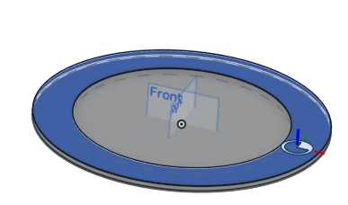
Could I do something as simple as take a narrow pie slice, let’s say 1/20th of the overall fan, and for simulation? Like in the following image?
And if so, would I just take the entire simulation domain and MRF and do the identical experiment, only with added symmetry boundary conditions on the pie walls?
Alas, induced flow is not symmetric in that setup: it will need to join magically other side of the pie. So, in my opinion, it is not a promising path…
Yes, you’re absolutely right. The boundary condition for flux across wall A is the negative of the flux across wall B. So there’s a negative symmetry for the radial flow, but there’s a positive symmetry for the axial flow.
The wedge boundary condition looks appropriate: Wedge | Boundary Conditions | SimScale. I’m going to try to play around with it. The one thing I don’t immediately see how to do is force the mesh to generate with only one cell thickness.
Well, you could mesh with different tools, but it is not well tolerated these days with SimScale software dev. Moreover, how to implement MRF? It is possibly not worth your time…