@DaleKramer & @Retsam, something for you? I think Dale you worked with someone recently (big thread) on something regarding this issue but for a rear wing (correct me if I am mistaken).
We did spend (mostly @DaleKramer, @dschroeder) hundreds of hours on those problems. Alas, you need understand what is going on under the meshing surface and it means that you need to spend some time reading what is already available on line in our forum.
I have read through this morning what you referred me to and still not exactly sure how surface refinement and boundary layer thickness interact with each other.
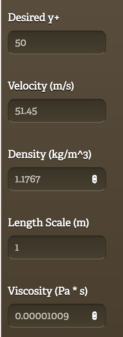
I used the Y+ calculator ( not pointwise as the browser didnt load for me)
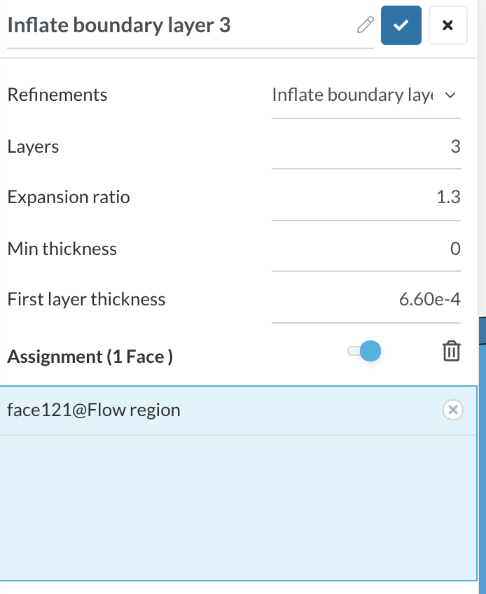
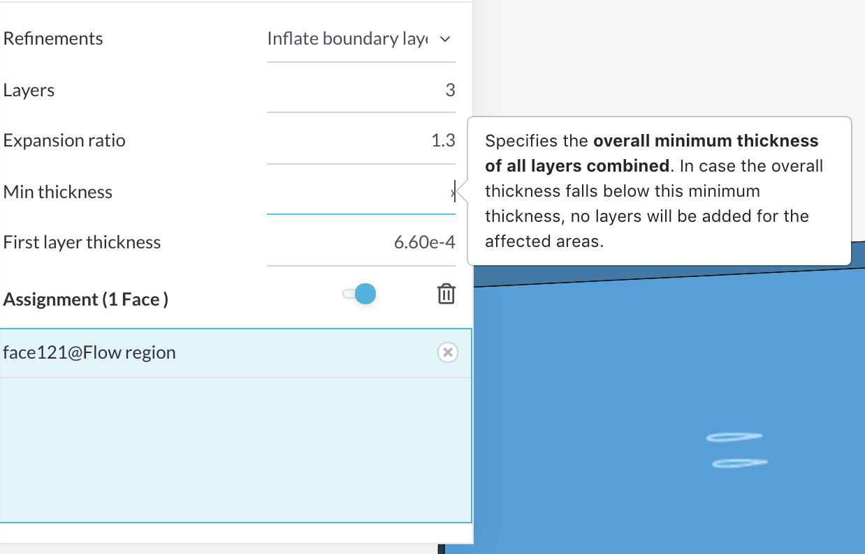
I have my first layer thickness set as follows but the definition given for minimum thickness is the overall minimum thickness of all layers combined. Which in my case would be a minimum thickness of 0.0026334. When I input this value it says that the minimum thickness must be less than the first layer thickness. Where have i gone wrong in my understanding?
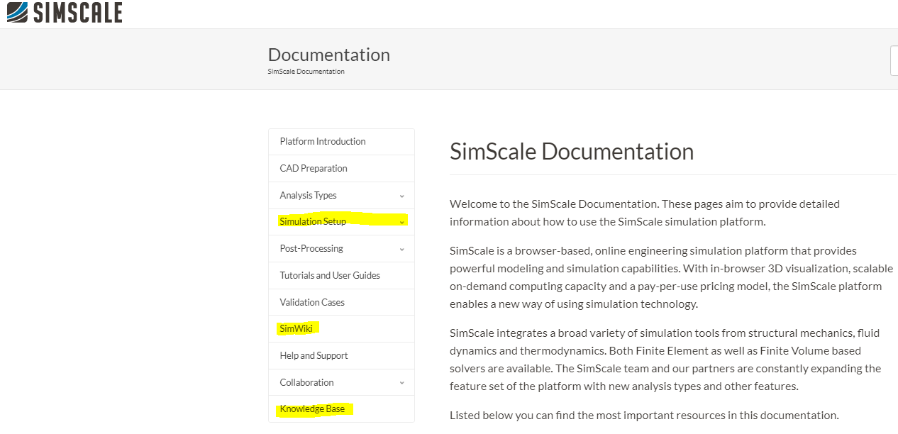
As Retsam said, I do strongly recommend reading through this discussion to anyone getting into CFD as it is pretty much everything you need to get started and get a solid knowledge on meshing and simulation setup.
I do not recall such an issue covered in one of those discussions, and I don’t have any experience with the non-parametric mesher (and i suggest using the parametric hex-mesher, since you’ll be able to have much more control), but something similar happened to me on a similar airfoil project.
I’ve also never worked with Enclosures, maybe you should have a look at Dale’s setup in a similar approach.
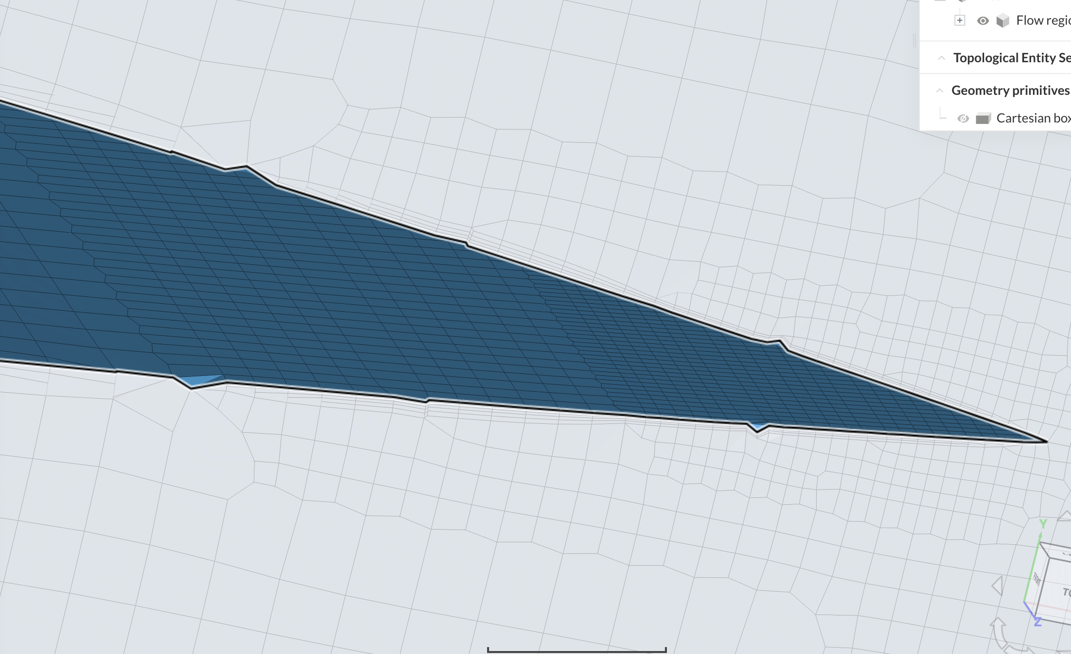
What worked in my case, using a solid body for the airfoil geometry and a cartesian box as a Meshing Box, was making the airfoil larger than the box, so that their edges were not coincident.
Edit:
I am pretty sure that the minThickness parameters refers to the single cell and not the overall thickness: if the size of the layer being added is less than that parameter, the layer won’t be added. I know documentation can be a bit confusing at times.
@ptreacy as ada_corte said i would highly suggest using the full HEX dominant parametric mesher as there are significantly more controls over the mesh.
Here is a basic overview of how the mesh goes through each step, castillation, snapping, layer addition etc…
I would also recommend spending some time going through all of the documentation provided by Simscale as most areas are quite thorough.
If i remember correctly, i also had problems when i simply set this value to 0, so try a very small number as Retsam suggested, like 0.00001.
Something else i just noticed that is wrong with your first layer thickness, which is for some reason Final layer thickness in the full parametric version … this is based off a source of confusion i had with something called relative and absolute layering. This is designated in the HEX dominant parametric mesh tree in Simscale as layer size toggle ON = relative /OFF = absolute.
With relative layering used (layer size toggle ON) the final layer thickness is not that at all… i wish Simscale would fix this. With relative layering, the first layer thickness is the RATIO of this final layer thickness to the surface cell size.
For example if your surface refinement is level 8 which equals a 3mm cell size, then having a 0.5 value in the final layer thickness input would result in a 1.5mm thick FINAL layer, which you would have to then calculate back with the expansion ration to get a first layer thickness that matches the Y+ you desire… confusing
Relative layering takes the surface cell size RELATIVE to the boundary layer cell sizes . This means the boundary layers will grow/shrink based on the neighboring surface cell size.
In absolute mode (layer size toggle OFF) the final layer thickness exactly as it says, the thickness of the final layer. Absolute layering also does not change the boundary layer cell sizes in relation to the surface cell size, so whatever settings you give, it stays like that over the whole geometry and no layers are deleted.
 I think Dale you worked with someone recently (big thread) on something regarding this issue but for a rear wing (correct me if I am mistaken).