I read several documents in Simscale, but it seems the documents are based on the simple geometry. My work is based on more complex STL file, and I just need the internal flow region to see how air circulation is going on. I would use k-omega SST model with certain air inflow velocity (ex. 40m^3/h).
Please help me to make the simplified geometry for the internal flow extraction!
(By the way my project is private, but I made it “share with support”. my ID dcb68ae3ee0645)
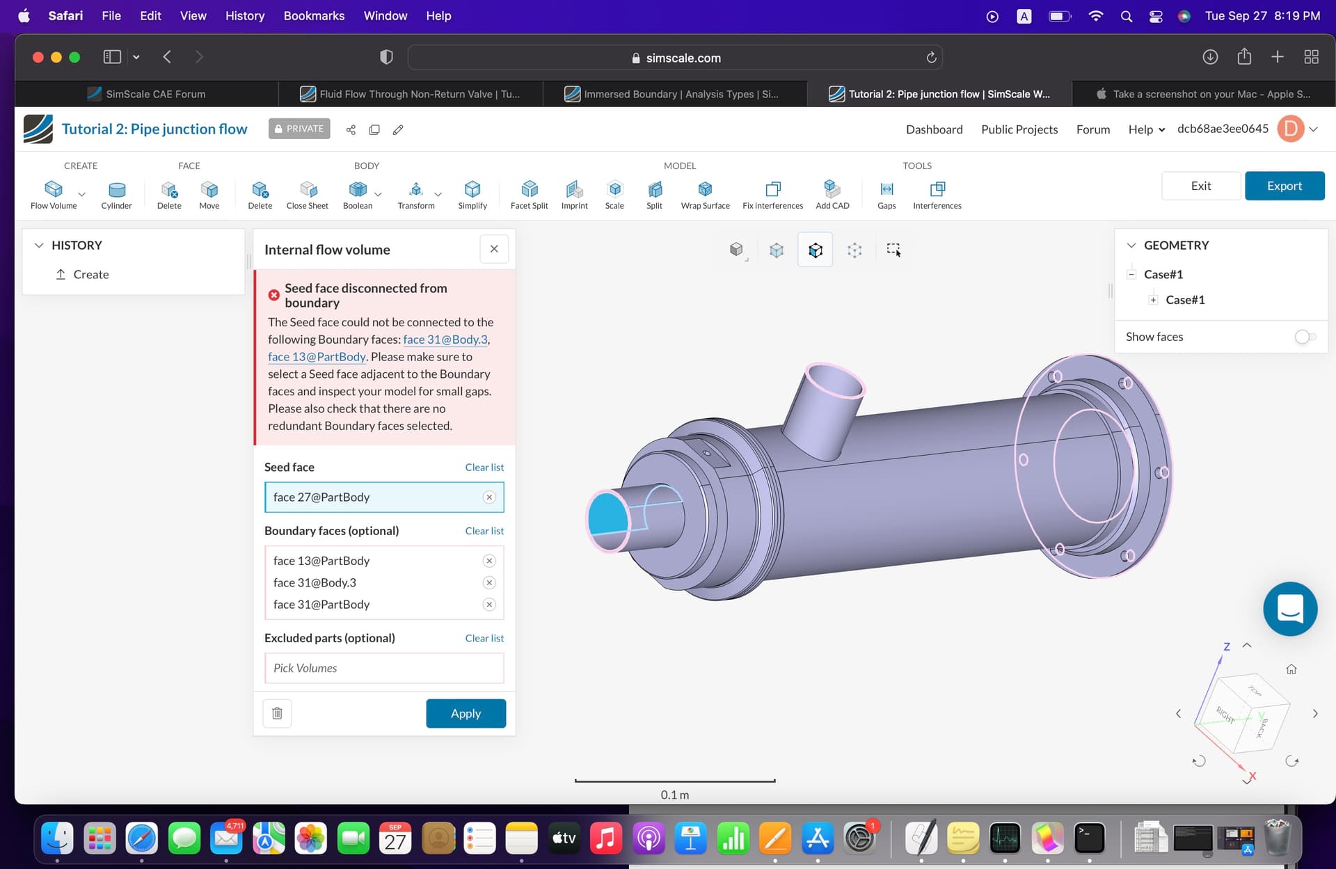
Hello, and thank you for using the Forum. The error you’re facing while creating an internal flow domain can be caused when there’re small gaps between entities, or when the faces are not splitted at the edge of intersection. Since the faces are not splitted and can not be connected properly, internal flow volume fails.
Usually imprint operation can be used to split faces accordingly when two solids are touching each other. However, in your case there seems to exist gaps between several faces which makes imprint operation not possible. I’m sharing an example below, two faces that have a gap between them, but the upper surface should be splitted accordingly.
What I would recommend is to remove these gaps with Move command in SimScale CAD mode, or in your CAD tool, and split the faces accordingly. Then you should have no trouble using the internal flow volume extraction.
Hope this helps.
Hello Kaany, thanks for the reply. But the point is that I can’t find the gaps in my model as you can see here. Moreover, I am not used to fix things in CAD mode of Simscale, let me know what should I do Simscale CAD mode to make the STl file to be available for the internal flow extraction.
Hello again! To double check, is your geometry in .stl or .stp format? It seems like the geometry is in .stp format, and the issue is independent of the file format.
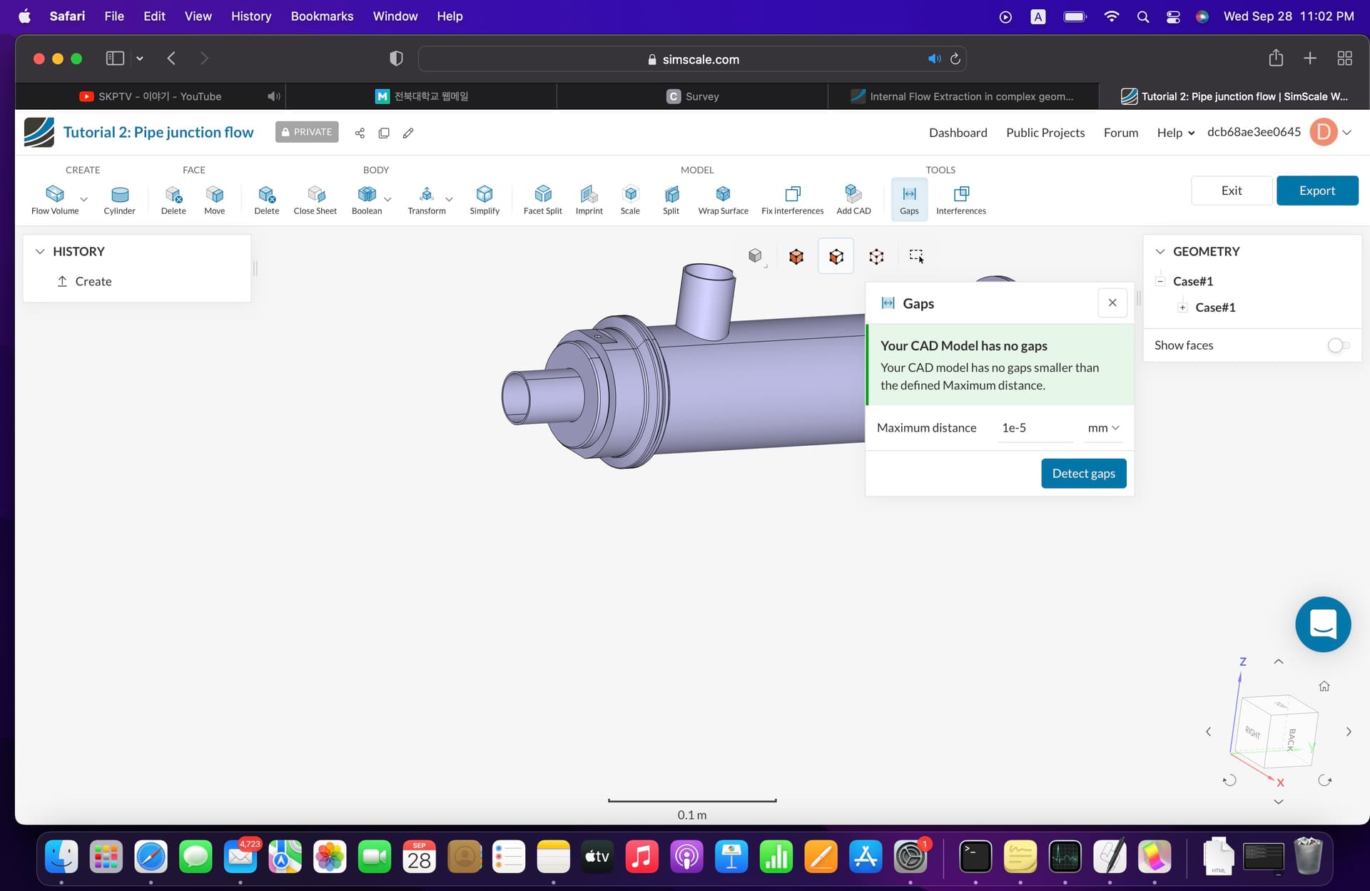
Gap distances in the geometry actually higher then 1e-5. Once you investigate the gaps with 1e-4 distance, you’ll see that there are 9 regions with gaps. You can visualize these parts that have gaps between by using the tree that’ll appear. You can use Move command in the CAD mode to solve the issue, or you can go back to your own CAD tool for necessary clean-up operations.
Hope this helps.