My flow domain is a block with a cylindrical void inside. I need to pick that interior face to measure force on but I’m having trouble getting Simscale to let me do that. That interior face doesn’t seem to show up anywhere. Thanks.
Please provide a valid link to your project where you have that simulation domain with a void cylinder inside.
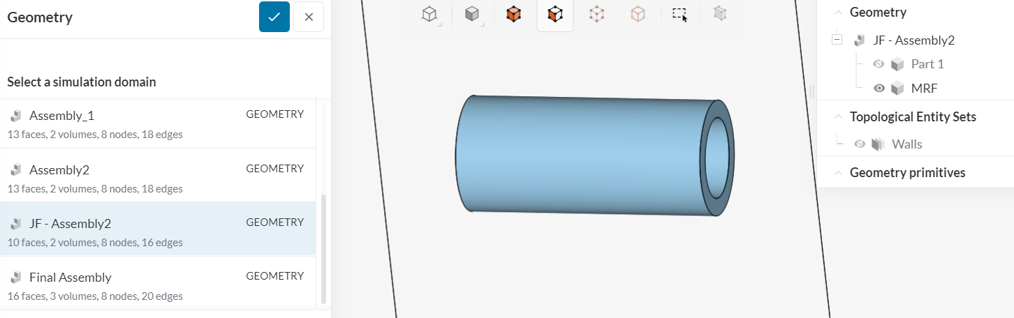
Hi, I’m doing what you suggested earlier. My issue now is selecting the face to compute the Magnus force on. Part 1 is the flow domain and it has an inner surface. Thanks.
Your ‘Incompressible 12’ geometry, Part one, has 6 faces (box). There is no internal void cylinder.
MRF zone is a pipe in your case (why, it should be a cylinder?), it has 4 faces (should have 3). So this explains you cannot select face which is not present in geometry.
Take care,
Retsam
1 Like
Thanks for your help Retsam! Please clarify a few points for me.
-
Is the MRF zone for air moving around the cylinder (a boundary layer), or just the volume of the rotating cylinder? For the Magnus effect I need to establish what the radius of the physical cylinder is so the simulation knows.
-
If it is the first case, how thick a boundary layer should it be? If it is the second case, I take it that it should be the volume of the cylinder and the domain should be everything except that void.
-
In either case, does there need to be a small gap between the MRF and the domain (part 1 in my case)?
I used a pipe shape because I interpreted the situation as in the first case above and I didn’t care about rotating air inside the cylinder. I was actually using JF-Magnus 3 and I thought I had a void? Anyway, I couldn’t figure out how to get the force on the void so I used the walls to get the reaction to the force on the cylinder. My numbers are about 80% of the expected value from simple theory.
Thanks again,
Robert
@Robert01: I hope you did study my Magnus cylinder project and remaining questions are just last roadblock you need to clear.
Terminology comment:
Boundary layer (BL) in CFD is a volume where specific simulation models (like k-omega-STT) use appropriate solvers. Knowing the fluid velocity, you can defined the BL for your simulation (with Y+ calculators). This is a vast separate topic you may study.
- For internal CFD with MRF, MRF is a part of simulation domain, bigger than your rotating part of the geometry. If your rotate a cylinder (so you have 3 faces you can calculate forces on), your MRF zone should be also a cylinder. Meshing ‘with cell zones’ will do necessary to create appropriate mesh around your rotating cylinder.
- For Manus effect modelling, you should have MRF only slightly bigger than rotating cylinder (3 - 8 % [my estimates]).
- No gap, but again for Magnus effect, you need to know and generate BL (currently you have it done automatically and it may by fine for your tests). However your last mesh is unusable (Mesh clip). See below:
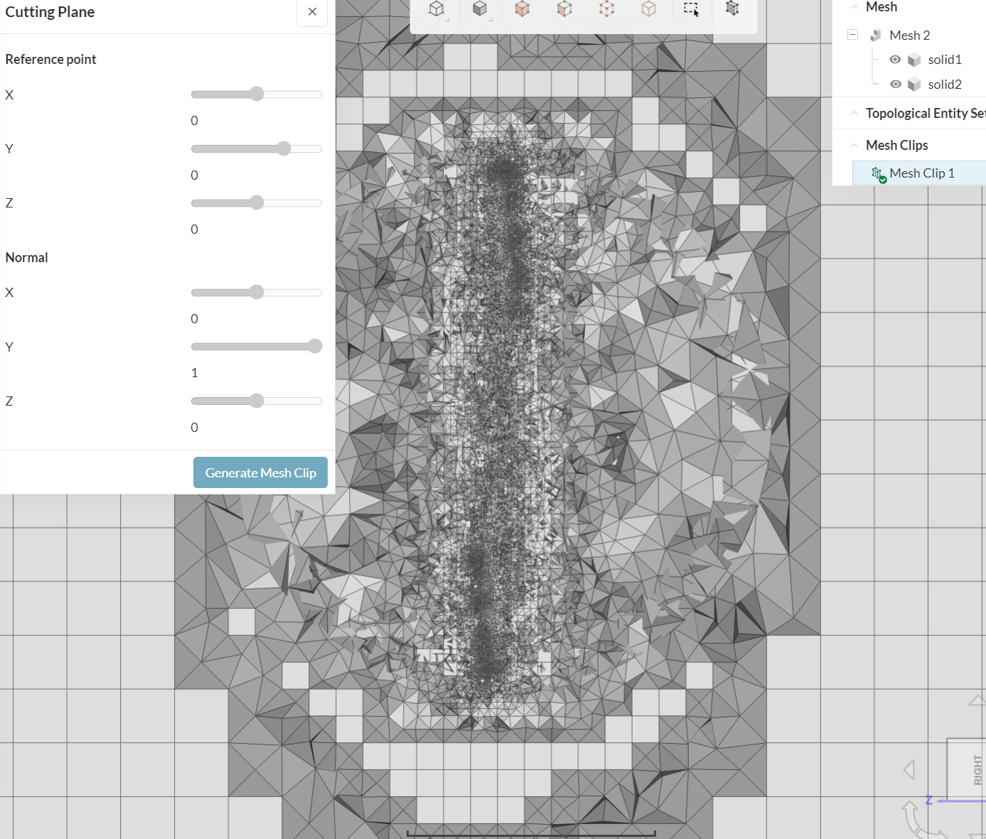
Take care,
Retsam
2 Likes