My project is SimScale
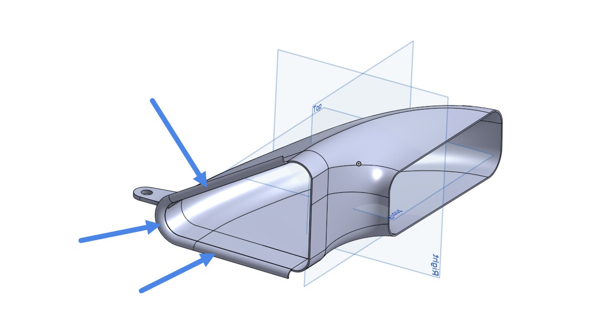
I am trying to model the airflow through a Nissan Skyline air intake scoop. (This is the CAD of just the intake - Onshape)
When I try and build some geometry in CAD to setup the correct boundary conditions, I struggle. What I’m trying to experiment with is optimum bellmouth shape, and so I’m trying to simulate that portion of the intake being open to atmospheric pressure, whilst the “engine side” connection is subject to an outgoing mass flow rate, roughly equal to the engines consumption at high revs.
What I’m having issues with is that I am using a “shell” in cad to build the box around the intake to the object to try and simulate atmospheric pressure, but what is happening is the flow is running through the walls of the shell, rather than going through the part. This is causing my simulation to fail and obviously isn’t what I’m trying to achieve. What would be the correct way to set this up?