Here’s a link to my project. It’s public. I’m trying to simulate this turbine rotor turning when wind is blowing at it head on at 15 m/s. Sounds pretty simple.
This is my first CFD ever so I’ve been using this tutorial https://www.youtube.com/watch?v=V7uYORB116k&t=1998s and after defining meshes I click on materials and it asks me to select the fluid material and volume.
How do I define a volume? I can’t select the mesh volumes. I tried the flow volume option in “edit in cad” mode but then whenever I try to simulate it says “a setup with 2 regions is being used in a 1 region analysis type”. Every tutorial I see also literally deletes the turbine from the CFD and replaces it with a perfect cylinder that is then negated in the flow volume, which is pretty pointless since I’m trying to model this specific rotor. Very confused right now.
Hello, make sure to have a look at this page - it contains an example for your specific application.
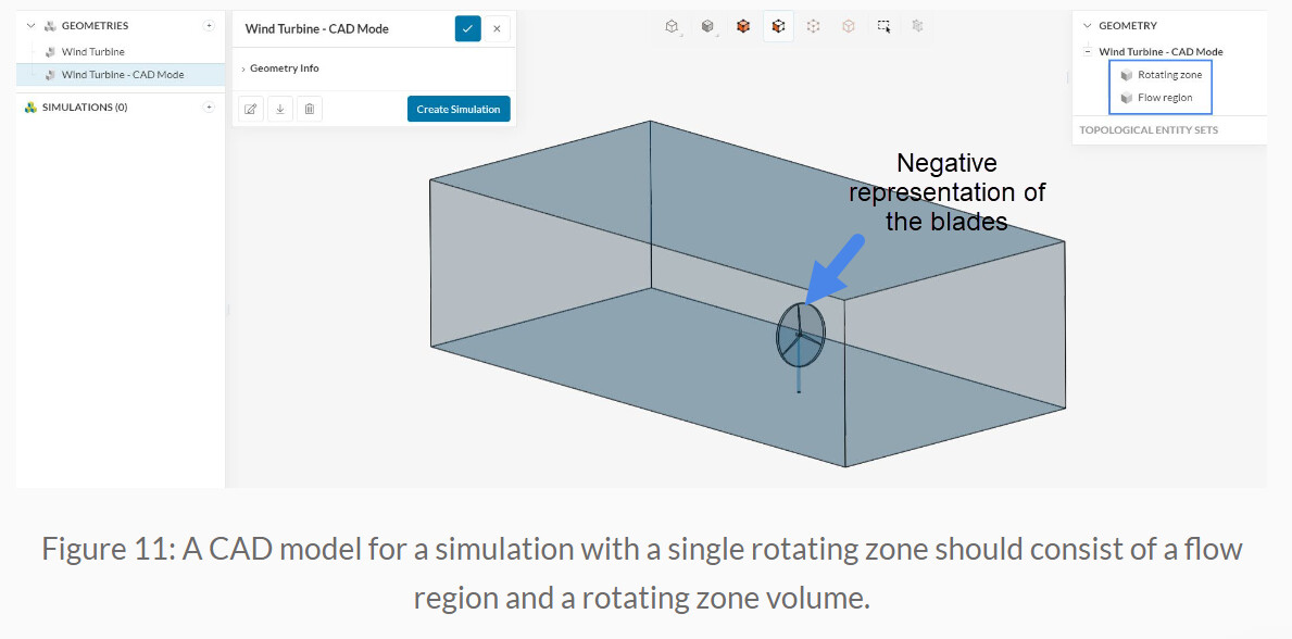
Note that, despite the presence of the cylinder, the blades will still be captured by the flow region once you run the flow volume extraction. You will also need to define a rotational velocity upfront, during the simulation setup.
Cheers
Hello. I’ve seen that example and tried to replicate it, but after I create a cylinder around the blade in cad mode, and delete the body, there’s no negative visual representation, I just see a flat cylinder in a flat ‘flow volume’. And the tutorial I watched (the youtube video linked) just make square geometry meshes without ever defining a flow volume in cad mode. Also I have not found a prompt that asks me to define rotational velocity.
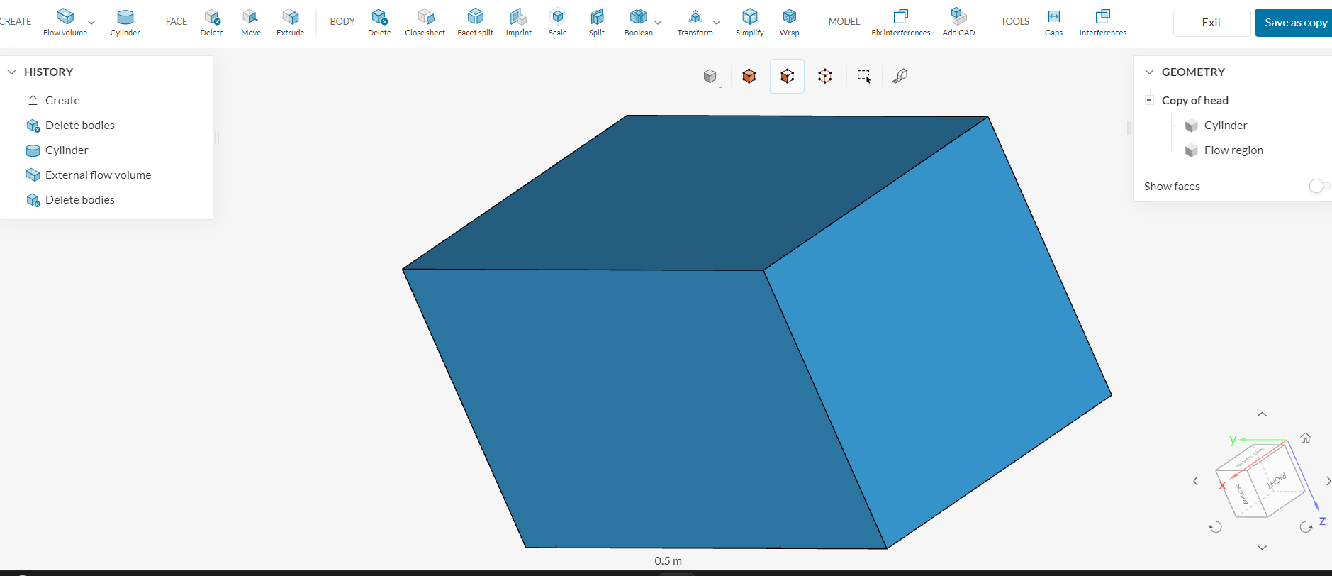
here you can see that I’ve made a cylinder, flow volume, then deleted the body of the rotor, and all I see is a massive cube and a shere. The simscale project should also have this now as “copy of copy of head”. This is very different from the tutorial which shows two low opacity volumes and a negative representation in black.
Maybe is the issue that I imported the rotor head as a .stl file? Because I got these blades from qblade and whenever I tried to import them into onshape as a solid the cad would look jagged and have holes.
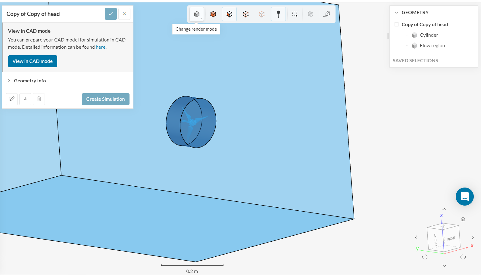
The negative representation of the impeller is right there - this is from your model: