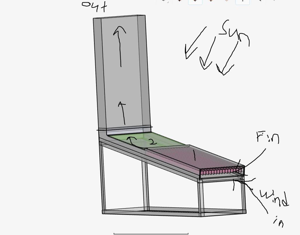
is the solar pV panel. its surface was exposed to sunlight.
is acrylic board. let sunlight penetrate but also exposed to sunlight (involve convection?).
-the fin will be also need to set having heat convection as received heat from 1 and release direction toward wind contact surface.
-the wind velocity 0.2m/s to 0.5 m/s.
the flow volume has been created as internal flow. which from the picture, the arrow was showing the air flow track.
looking simple. But i’m definitely weak in the simscale feature.
so may you provide me the detail of simulation process/step/which feature to use.
The “Conjugate heat transfer” simulation type will be perfect for this type of problem.
There’s a bit to get your head around when setting up simulations like this so Id recommend watching some tutorials before you get started.
The tutorial below will introduce you to some of the core concepts: Conjugate Heat Transfer in U-Tube Heat Exchanger | SimScale
Good Luck!
hi dav,
i have been through the conjugate heat transfer tutorial that you has suggested.
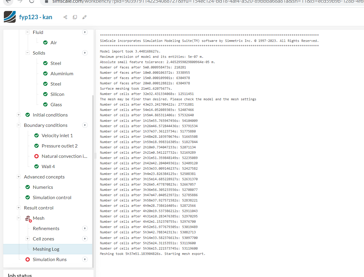
Unfortunately, i was not able to create my meshing. may you lend me some help here?
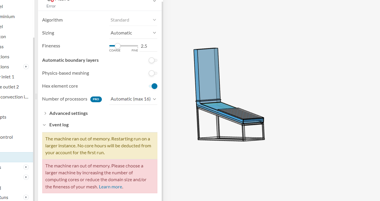
now the meshing ongoing was in fineness(3), i have been tried out fineness (5)&(8) but both of them has failed. notify me with saying the machine run out of memory.
Hi,
The machine will likely be running out of memory because the mesh is too large. ~50million cells is a lot for this kind of problem, so first port of call would be reduce the mesh size. This can be done a number of ways:
Lower the fineness slider. I can see you’ve already done this and the mesh is still large which leads me to suspect that there are likely some abnormalities in the geometry. This leads to the next options:
Remove any un-necessary geometry from the model. For example, is the stand needed in this simulation? If not, best to remove it, as including it will only increase mesh size and run time.
Under “advanced setting” adjust the “small feature suppression” setting. This setting essentially tells the mesher to ignore any small details under a certain size limit. That size limit should be set large enough to prevent your mesh getting too fine , whilst being small enough to maintain the fine details of your model. Given that the finest detail I can see in your model is some ~4mm thick wall sections, I’d adjust that setting to about 0.0005 (m) as a starting point. (roughly 1/10th of your smallest detail.)
Finally, if that doesn’t work, there may be a geometric error in your CAD model (like a sliver face or intersecting face etc.) This is actually pretty common. In that case you might be best to jump back into your CAD modeling software and try to fix the model from there.
hi @davey ,
I finally settle my model with the flow volume, and meshing.Here,
would be the latest model and i already run the meshing.
So far, i only assign the inlet velocity and outlet pressure.
Could you help me by telling me what should i do next for achieve the simulation.
i been to the conjugate heat transfer tutorial, but i wasn’t sure to apply the boundary condition for the heat transfer between (1) panel and the fins. and then convection from fin to the air in the flow volume.
Glad to hear you got the model to mesh! What did you change to make it work?
Assuming I’m understanding your question correctly, if the mesh for the panel, fins and flow domain are in contact, then the simulation will automatically conduct heat between the 3 volumes. So you shouldn’t need to setup any boundary conditions for that.
I removed the useless ‘stand’ and do two separate part’s meshing. After that at the edit CAD of one part i just ‘add cad’ added the second part and union them. Then its done… And took even lesser time when meshing the combined model.
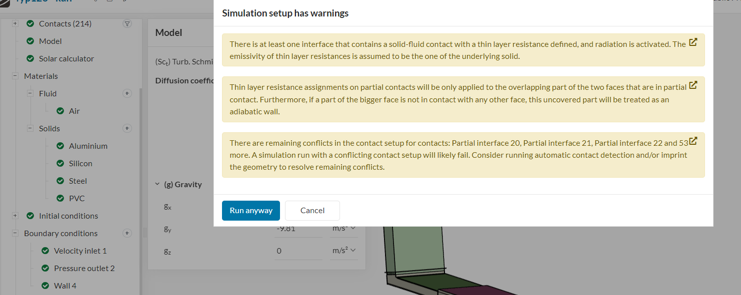
Thank you for your reply. As i checked all the parts should be in contact with each other. Where when i add a (wall and conve in/out) the simulation would fail. As notification showing this