Hi, I am trying to thermal analysis of a raspberry pi in an enclosure. I would like to show the heat dissipation and heat airflow when a fan is installed. I am a beginner and have various difficulties and can’t find a solution for them.
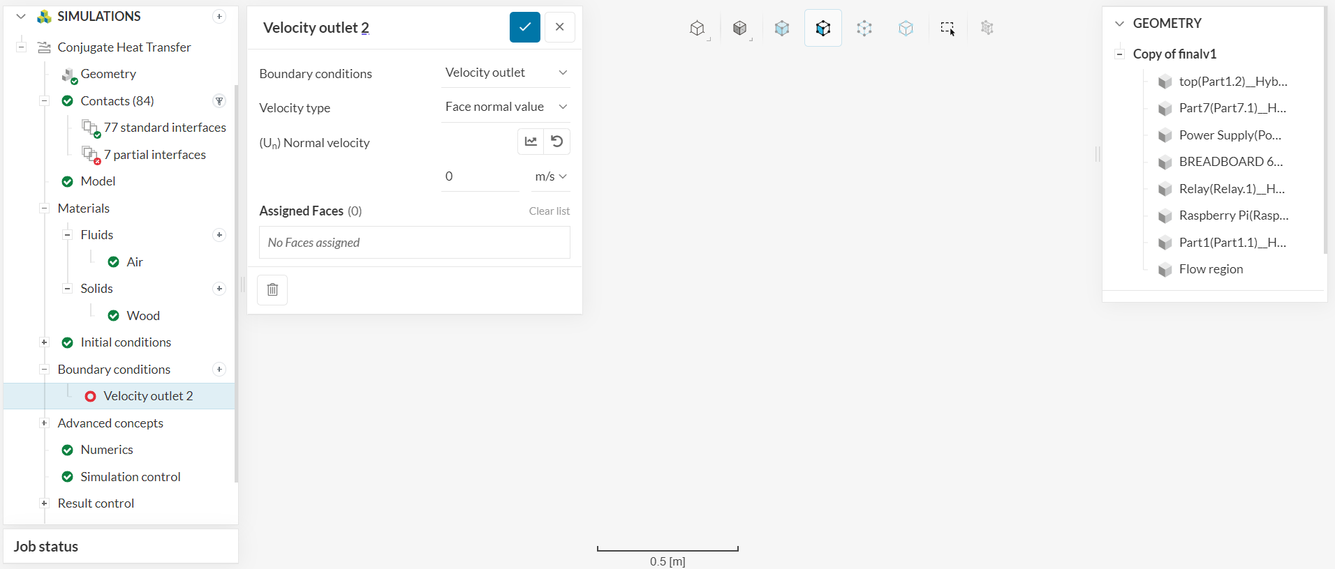
Having errors where there is partial contact, and it can’t be fixed with interference tool. Furthermore, the chip which is the heat source cannot be selected as it is not a face. I would like to select the chip to be the heat source when I set the boundary wall.
I had a look at your project, but I found that the simulation run was deleted and all of your setup is clean. Thus, I can not find what the errors are and their source.
What I can see from the geometry is that you need some cleaning-up to do:
Simplify the parts to primitive shapes.
Fuse solid parts that are the same material to lower the count of contacts.
Assure that contact faces are in full contact.
Remove small faces and unnecessary details.
You can do most of this work in the CAD Edit Mode:
Otherwise you need to go back to your CAD tool for the cleaning task.
I have tried to simplify with this new attempt but there is still partial interference. I have snapped the components to base in CATIA, but the problem persists in simscale.
And how do I activate the rotating cube in the bottom right-hand corner? It is missing for me, but I have seen it in videos online.
Thanks for the prompt reply. I have managed to fix the issue using imprint in CAD tools.
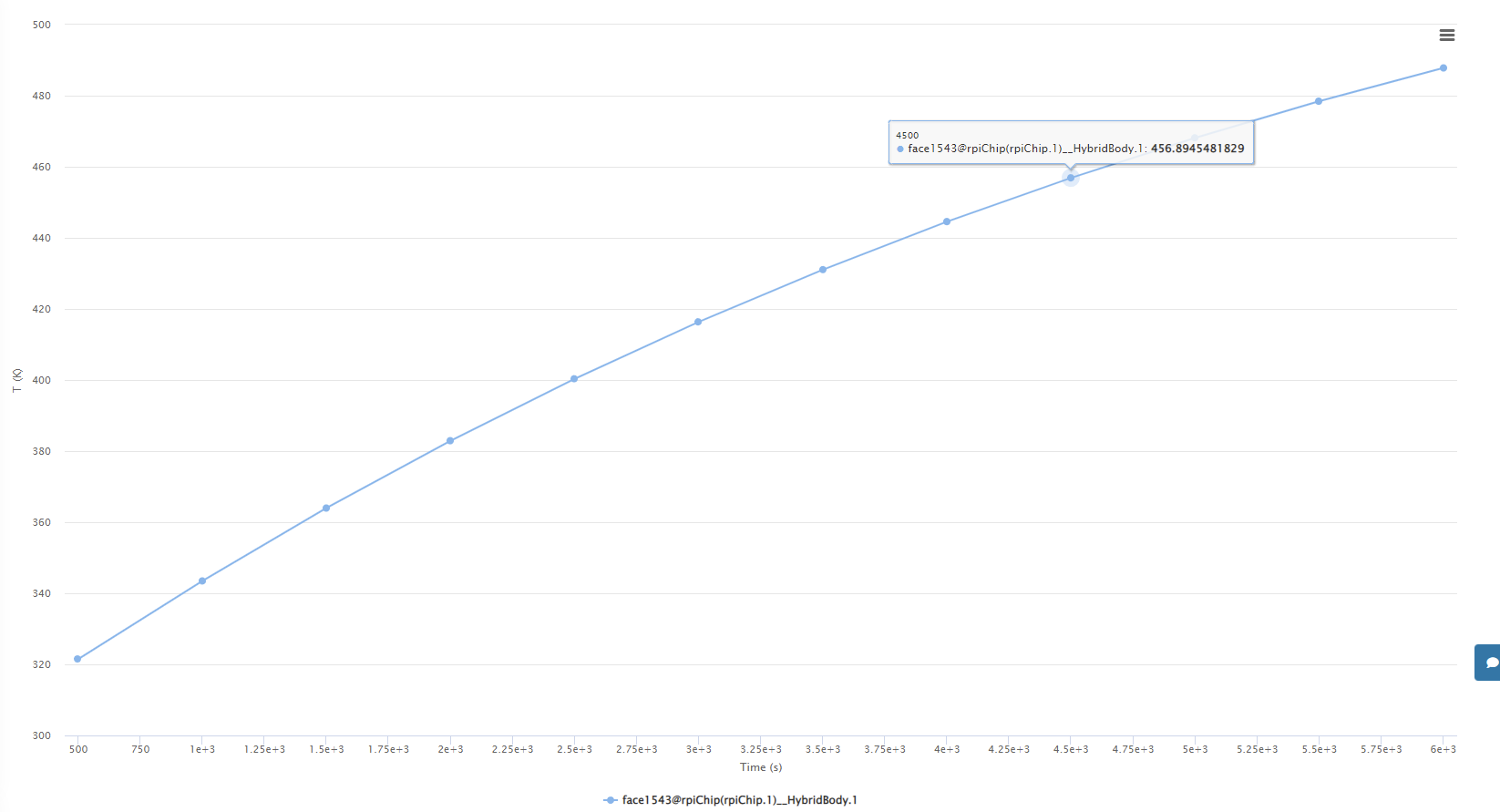
Currently a problem surfaced for me after successfully running the simulation. I have a chip which is made up of silicon and has absolute power of 3.7W. I would like to show that airflow will help to cool the chip.
In real life scenario the chip is supposed to have a temperature of 75 degrees celsius. However, Simscale is showing the temperature to exceed 100 degree celsius despite having cool air of 25 degrees celcsius entering the compartment. Furthermore, an increase in airflow for cooling does not help to decrease chip temperature.
Is there a way to show the chip temperature reaching maximum of 70-80 degrees celsius and there is a drop in temperature due to increase airflow. Any help will be greatly appreciated.
You can take a look at the last 2 simulation runs, “Sucking Air In V3” and “Blowing Air Out V3”.
I will contribute with a reasonable number of comments, in addition to what @ggiraldof posted.
Your approach should not be “a way to show the chip temperature reaching XXX” but explain why your modeling results do not match the experimental measurements.
SimScale thermal + fluid module solves a fluid flow problem with energy transport and couples it with a thermal model for solids. Many things can go wrong here if many of the numerical models used to describe the physics of the problem are not being considered. For example:
Are you considering radiation? It appears that you are not.
Did you set real turbulence values at the inlet boundary for the airflow? As the cooling flow does not have a duct to develop, the cooling flow will be governed by the turbulent values prescribed in the inlet boundary. As you know, turbulence has a large effect on the convective heat transfer coefficient and on the removal of heat from the chip.
Did you carefully create a boundary layer around the chip to comply not only with the fluid boundary layer y+ requirements of your turbulence model but also with the thermal boundary layer requirements?
Modeling convective cooling is not easy. Not even in a flat plate, where the simplification using 1D models to determine the convective heat transfer coefficient is not trivial.