I created a new simulation project called 'Heat exchanger - CHT simulation':
This project
More of my public projects can be found here.
I created a new simulation project called 'Heat exchanger - CHT simulation':
This project
More of my public projects can be found here.
Since the Newtonian era, the empirical heat relation that entailed the proportionality of the rate of heat transfer between two bodies to the temperature difference between the bodies along with a heat transfer coefficient had always been used for industrial applications. Owing to the evolution of computers and a recent discovery by a group of former Soviet scientists, a Conjugate Heat Transfer (CHT) model was developed.
CHT allows the simulation of the heat transfer between Solid and Fluid domains by exchanging thermal energy at the interfaces between them. Moreover, this analysis type eliminates the need for the heat transfer coefficient. The typical applications of CHT include simulating heat exchangers, cooling of electronic equipment, and general-purpose heating/cooling systems.
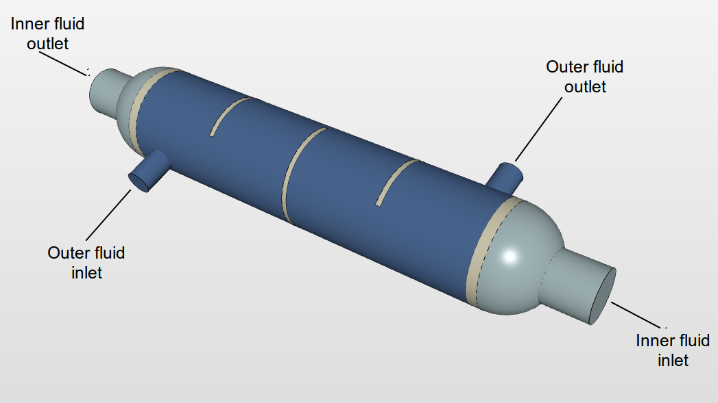
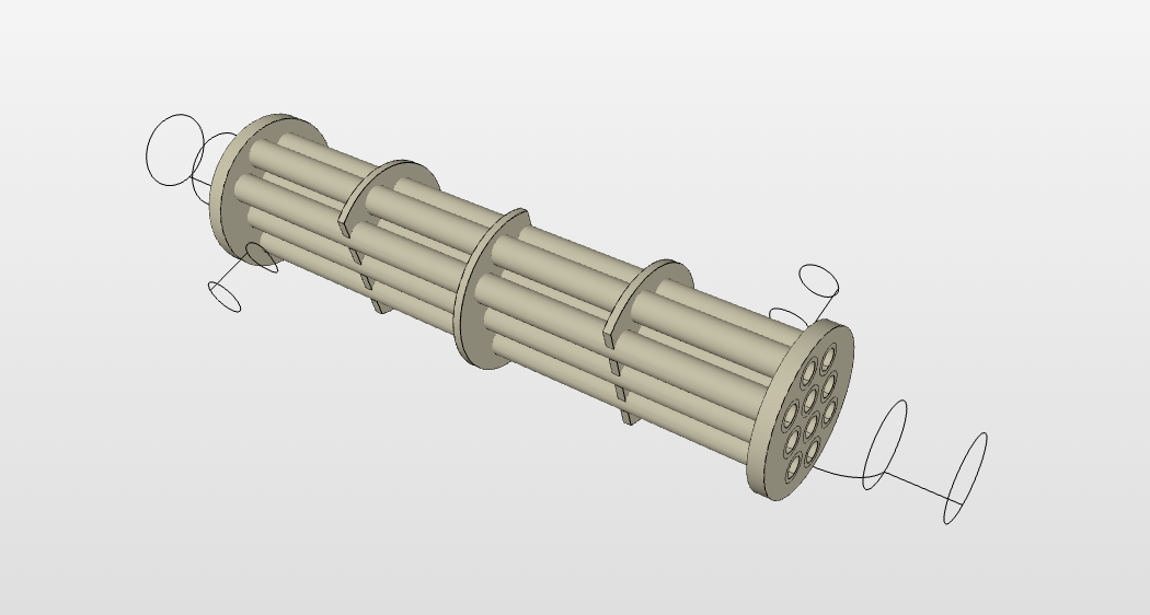
The current project contains an analysis of a Shell and Tube Heat Exchanger. This is comprised of:
Pipe volume (solid): - Essentially, the housing of the system plus the volume of the pipes containing the working fluid.
Inner fluid volume: This is the fluid flowing inside the heat exchanger tubes, absorbing heat from the outer fluid.
Outer fluid volume: Fluid flowing through the shell, releasing heat to the inner fluid.
With the help of the SimScale platform, we intend to study the heat transfer process occurring in a heat exchanger using the conjugate heat transfer model. The model is based on a strictly mathematically-stated problem, allowing the physical processes and solutions of the governing equations to be considered separately for each object in two subdomains[1]. This makes way for an independent analysis of both the flows (external and internal) and eventually coupling them to plot the effective heat transfer.
A CAD assembly keeping in mind the 3 components as described above has been prepared for the purpose of this project. The images shown below depict the configuration of the fluid volumes and the pipe geometry to be used:
External Geometry of Heat Exchanger
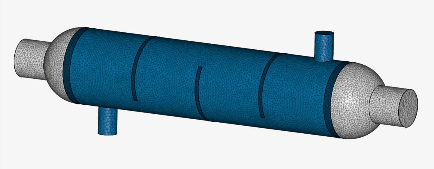
When dealing with CHT, we require a multi-region mesh to have a clear definition of the interfaces in the computational domain. Such a mesh can be created by using SimScale’s highly automated standard meshing tool. Standard mesher will generate tetrahedral elements near the boundaries, while hexahedral elements are generated near the core.
Standard mesher is used to generate the mesh for the 3 volumes (1 solid and 2 fluids) followed by creating refinements. Two region refinement zones are generated to enhance that the fluid flow and heat transfer is captured successfully.
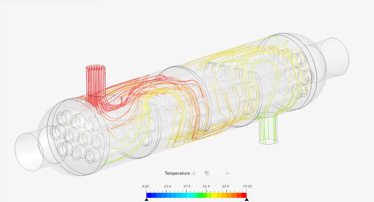
A steady-state simulation is carried out using the Conjugate Heat Transfer solver with k-w SST turbulence model. The outer fluid is considered to be at a higher temperature (releasing heat) and the inner fluid at the lower temperature (absorbing heat).
The image below illustrates the flow of the temperature streamlines in the shell of the boiler. As can be seen in the image, the temperature gradient of the Outer fluid is much steeper at entry and gradually decreases with the furtherance of the fluid across the shell.

Can we download the project file to be run on Ansys?
Hello @avin007,
SimScale works on the basis of OpenFOAM code. So it is not possible to run the project file directly in Ansys. You can download the geometry and setup an equivalent case in Ansys!
Sam
Thanks for the prompt reply!!!
Hello Sjesu,
Is it possible to simulate a natural convection flow in the CHT module? I mean for example, a fluid domain inside a solid housing and another fluid domain enclosing this housing. All flows are due to natural convection.
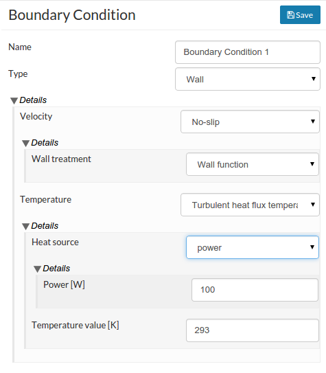
Can i define a heat source (W) in CHT simulation?
Thx in advance
Hello @jgonz,
Yes, this is possible! I believe we don’t have any model of this case in our public project list, to point it as an example to you.
You can continue with the setup of this case and we’d be happy to offer any possible support!
This is also possible! The definition can be done as shown below.
If you prefer to give a volume heat source - this is not possible. We have it on our feature request list at the moment.
Sam
Hello Sam,
I appreciate your help.
For a CHT simulation is mandatory create a solid for every fluid region (fluid region for external and internal flow)? What role play here the material point definition?
In a first aproximation, i have a solid region as lamp housing, inside this one i have a fluid region representing the air enclosed and another solids regions representing another electronic components. The fluid around the housing will be considered by a wall boundary consition.
In a next way i want to add to the last model the fluid around the lamp as a fluid region.
By now i am working in the first aprox. and i have some problems with the fluid region meshing. I have defined the material point inside the fluid region but i cant get the fluid region meshed. Any idea to fix this point?
thx in advance
Hi @jgonz,
Thank you for explaining in detail. I think you are referring to the following project, I have some clarifications in this regard.
Firstly, I see that the geometry is not in the exact way to define a multi-region mesh. The larger geometry (solid_10) seems to be overlapping the smaller geometry volumes. For multi-region meshing to be successful the geometries should not be overlapping, but the boundary surfaces have to be touching each other. Please correct the geometry and try to mesh it again. Also, since there are multiple solids I don’t exactly understand which are the solid and liquid volumes. Could you please clarify this as well?
With regard to the material point, this point is independent in case of multi-region mesh. Once you have the final geometry it is a safe bet to place the material point in the fluid volume. At the moment, it might be difficult to troubleshoot why a particular region was missing due to the geometry issues mentioned above.
Best,
Sam
Hi Sam,
I will try to be more clear in relation to the components of my project.
solid_0 = solid lamp housing ( external solid)
solid_1 to solid_9 = solids regions representing different solid components of the lamp ( sink, driver, covers,…)
solid_10 = fluid region representing the air volume inside the lamp
The solid_10 region is obtained from filling operation after solids regions were created and thats why i think there are not overlapping between them, The material point is placed in the fluid volum but i will try an another location.
thx
Plz tell me how to download the files of this protector, I badly needed it
Hello @jgonz,
A new enhanced mesh algorithm for multi-region meshing has now been deployed by our Product Engineering team. Please try to generate the mesh again. I hope everything should work as expected! Please let us know if you have any other queries with regard to mesh or simulation setup.
Regards,
Sam
Hi @bibhab,
What are the files that you need? Could you clarify what exactly you mean by a protector?
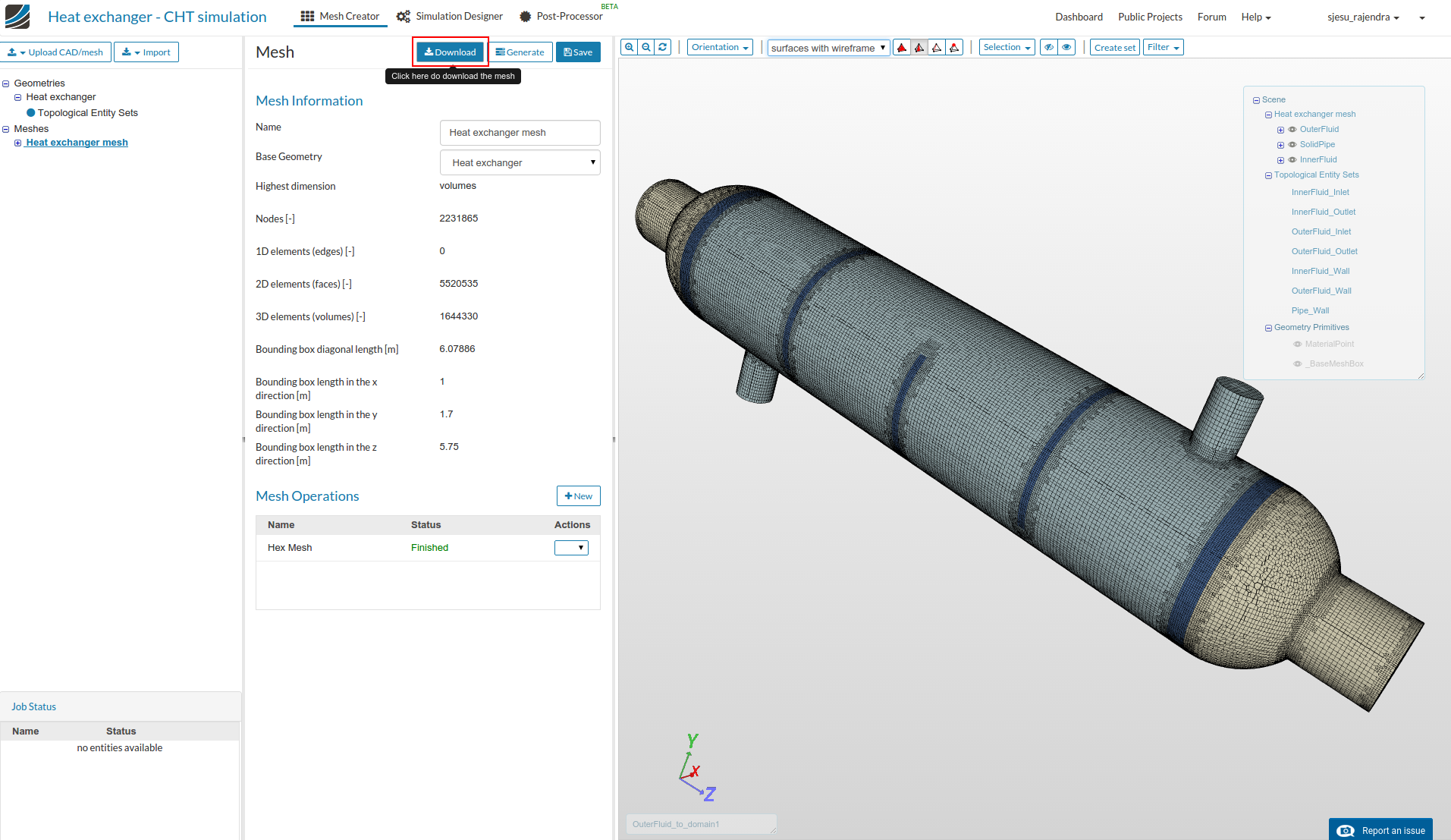
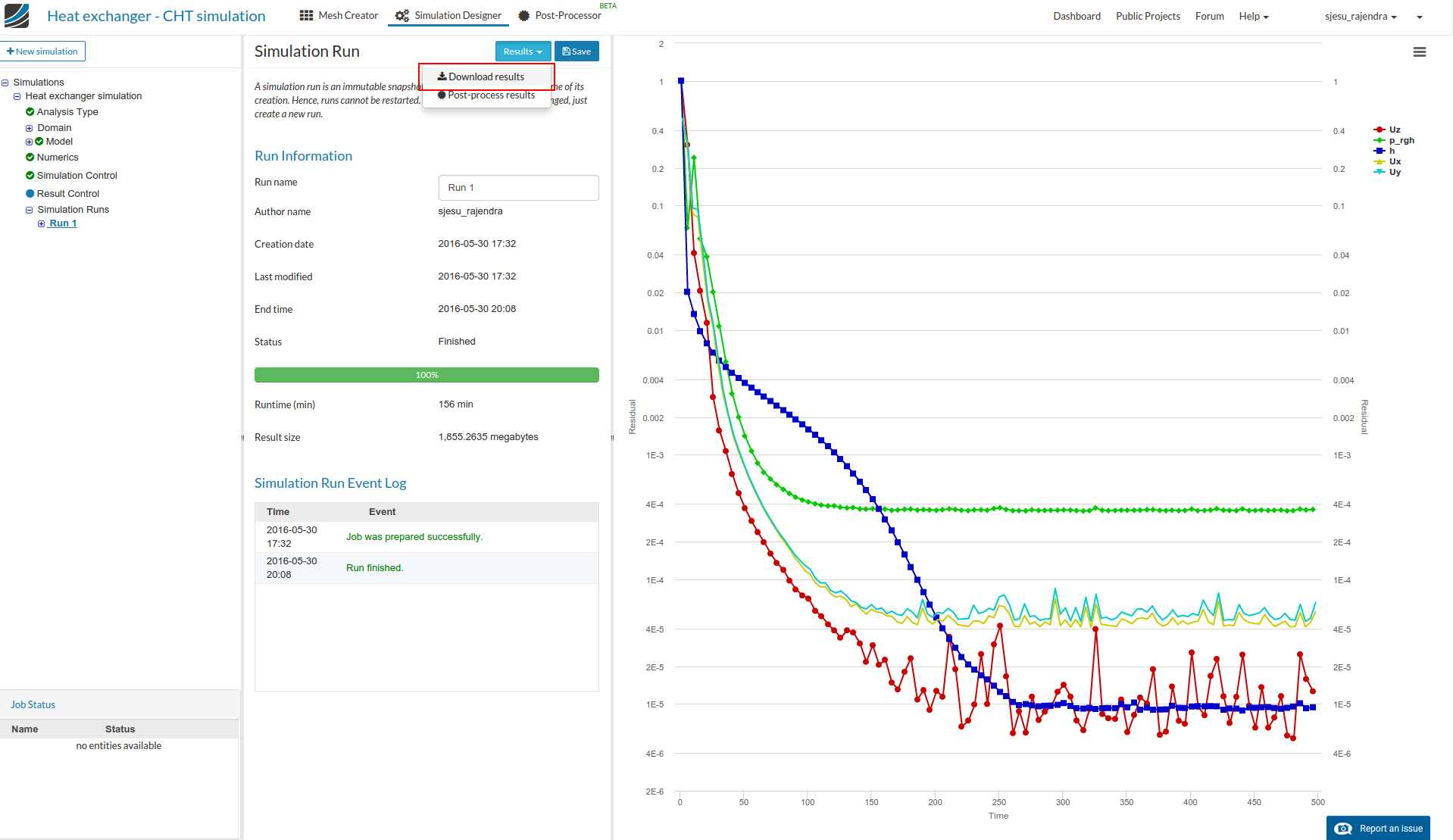
The possible downloads from SimScale platform are the mesh and the simulation run results, which can be done as shown below.
.
Please let me know if there is anything specific with which I can be of help!
Regards,
Sam
Thanx for the reply. My question is how to set up the case in open foam 3.0.1
Hey @bibhab,
Unfortunately SimScale doesn’t support OpenFOAM 3.0.1 at the moment. So the case has to be setup and run locally on your PC.
Sam
surely sir i will do it locally but can you please guide me how to mesh the heat exchanger in snappy hexmesh in openfoam without blockmesh
Hello Sam,
I am glad to hear these good news. I will try to generate the mesh again and solve this CHT simulation.
Thx
Quim
Hi @bibhab,
This is quite a big topic. You can look into snapppyHexMesh guidelines in online OpenFOAM resources. This is one of the docs explaining the snappyHexMeshDict.
I hope this helps! Please let me know if you have any other questions!
Regards,
Sam
Hello @riccardom,
The CAD model is a courtesy of my colleague Alex (@afischer). The point to be noted during geometry modeling for CHT case is that the different volumes (representing the solid and fluid regions) should not be overlapping, but the surfaces touching each other so that snappyHexMesh automatically detects interfaces.
Regards,
Sam