Hello,
I am fairly new with the program, and part of my project consists of simulating (CFD) the performance of a small sized glider we designed using very basic information. However, all the runs I attempted until now failed. The first runs ended in the error “Velocity field started diverging. Please check…”. I sought help, and in the end I had made mistakes on my region refinements. Correcting them still did not solve the problem, and now after numerous attempts, I am now getting a new error, which is “Gauge pressure field started diverging. Please check the mesh…”.
Project link: https://www.simscale.com/workbench/?pid=2460061441153204044&mi=run%3A16%2Csimulation%3A5&mt=SIMULATION_RUN
Hi there, and thanks for using the forum!
I think you are on the right track, and it is common for wing models with a sharp trailing edge to have divergence, due to mesh quality at that location.
I suggest you to add these refinements:
- Local element size over all the glider surface, to better capture the surface and edges.
- Region refinement with cylinder primitive over the trailing edge of the wing(s) to improve mesh quality at this location.
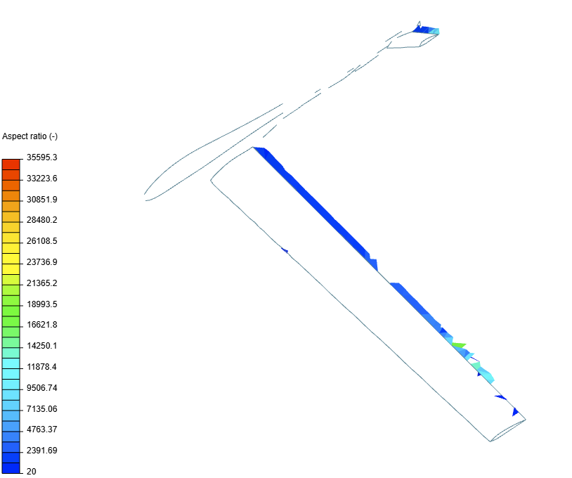
You can corroborate this fact if you go the Mesh quality module and create an Iso-volume plot on the aspect ratio:
Thank you very much! I was wondering what maximum edge length would you recommend for both of these operations?
I would estimate the length of the refinement based on the chord length of the wing. Say you want 10 to 20 cells across the chord. That should be a good starting point.
Sadly the simulations failed, even after reducing the max edge length. I still got the pressure gauge error.
I think it can still be refined a little more to better capture the curvatures.
Did you make any changes to the numeric settings?
No I did not change the numerics settings however did i notice I had a no slip wall on the gliders area does it have any effect on the simulation run?
The no-slip wall is the correct boundary condition for the body surfaces.
Please try the mesh improvement route, and report back your results.
Unfortunately, it still failed
Hi again!
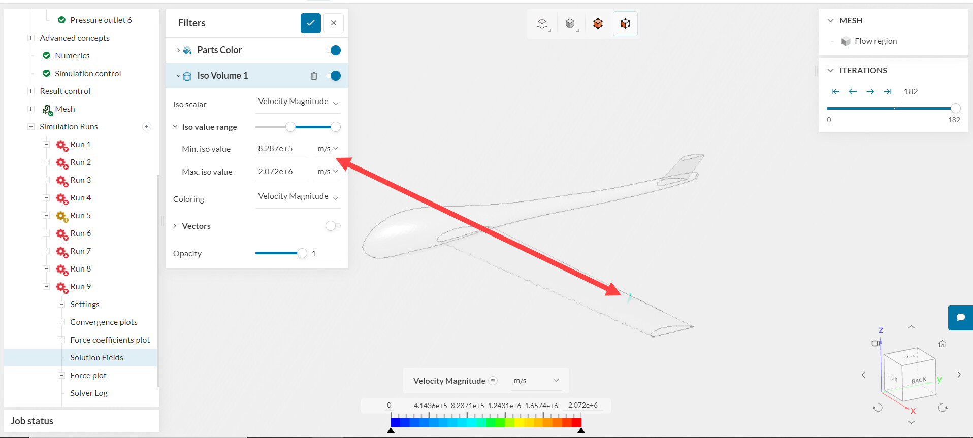
I think you still need a little more work on your mesh. For example, I noticed that your region refinement with cylinder doesn’t line up with the trailing edge:
Also, you didn’t tackle the edge on the tail wing.
Sorry if it may seem irrelevant but what do you mean by tackling the edge on the tail wing?
Of course it is not irrelevant, perhaps I am not using the correct terminology.
I refer to the smaller wing, in diagonal, at the tail of the vehicle. This one also has a sharp edge and in the quality plot above shows an area to improve.
Okay I will work on my mesh quality and report back.
Hello, I am having difficulty reducing my aspect Ratio quality metric to be low, in the isovolume chart the maximum number is always around 8000
I agree with Guillermo that the main issue here is the mesh. The simulation diverges around the trailing edge:
The usual approach is to make the trailing edge blunt and apply appropriate refinement levels.
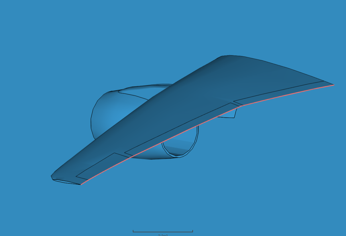
For example, for the compressible flow around a wing tutorial, if you pay close attention to the trailing edge of the geometry, you will notice the blunt section (red highlights).
You could also potentially try a hex-dominant meshing tool.
Cheers
Hello, I am not quite sure if I can modify my CAD design since that portion of my project is already complete and submitted (and another part of the project was made as well with that design). However I tried the hex-dominant tool and am currently waiting for the simulation results.
The simulation run with the hex-dominant tool worked! The VolumeRatio max was way lower that before with this tool, approximately 52, as opposed to the 2000-8000 I would get before. Thank you very much
The best advice I can give you is never to start with a full-body simulation such as this one. Do start with a 2D simulation of an airfoil, then move to 3D for the wing and then do the whole. Validating your modelling approach, especially the mesh distribution is of utmost importance if you want to obtain “realistic” results.