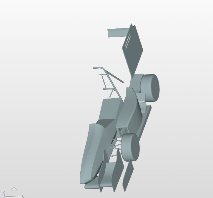
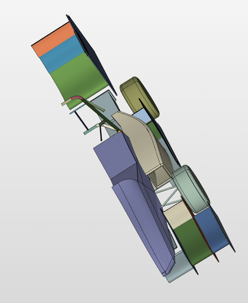
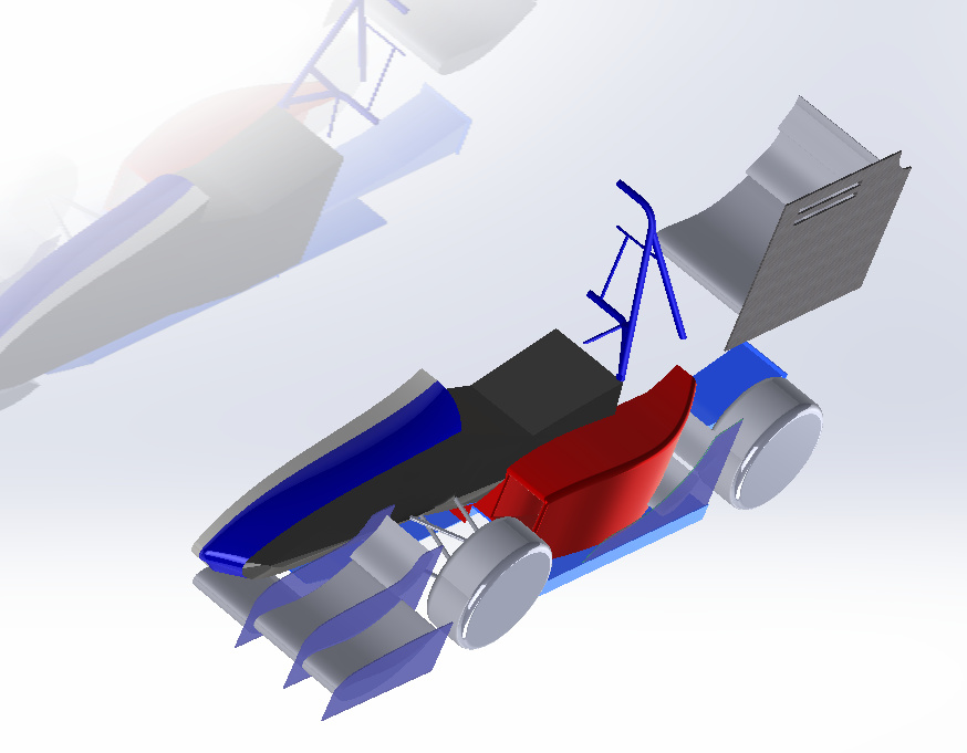
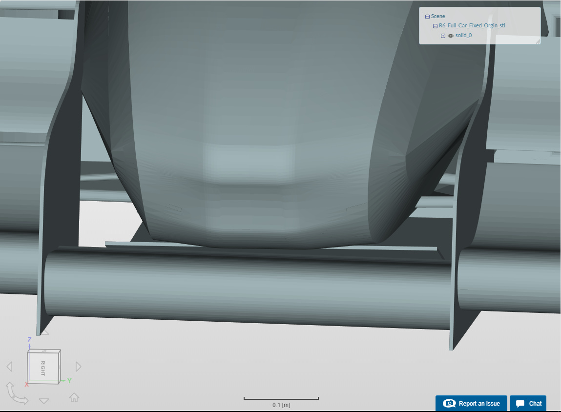
I have been trying to do a full car simulation for an FSAE car for a while now. At first I had to fix my geometry, because I had weird surfaces when the file was exported. I have since fixed my geometry, and now when I create the mesh I lose parts of my rear wing, front wind and sidepod end plate. It also looks as if the air guide inside the sidepod has also lost some surfaces.
I have made sure that all of the faces I required in my mesh were selected, and this result still happened.
Why is this happening? / How can I fix it?
Hi @mmccann - I took a quick look, indeed nothing obviously wrong with the geometry. I filed a ticket for the CAD/Mesh team to take a closer look at it. Will get back to you once I know more.
I have tried to make the mesh again with the automesh feature. The same problem occurred. I know you already submitted the ticket, however I’m just trying to provide as much information as possible.
I was wondering if anyone has taken a loot at the ticket? I really need to get this simulation going so I can prepare my design binder for competition. If no one has gotten back about the ticket, is there a chance you could try to take the geometry and make a mesh and see if I was just doing something wrong?
For the geometry you mentioned in the first post it seems that there are some intersections and the geometry is not watertight at all. Has this been fixed somewhere? Makes things definitely harder! @dheiny will get back to you asap!
You have to close open holes and make sure that there are no gaps that would make the fluid “go inside” the vehicle. You can do that with a CAD software of your choice.
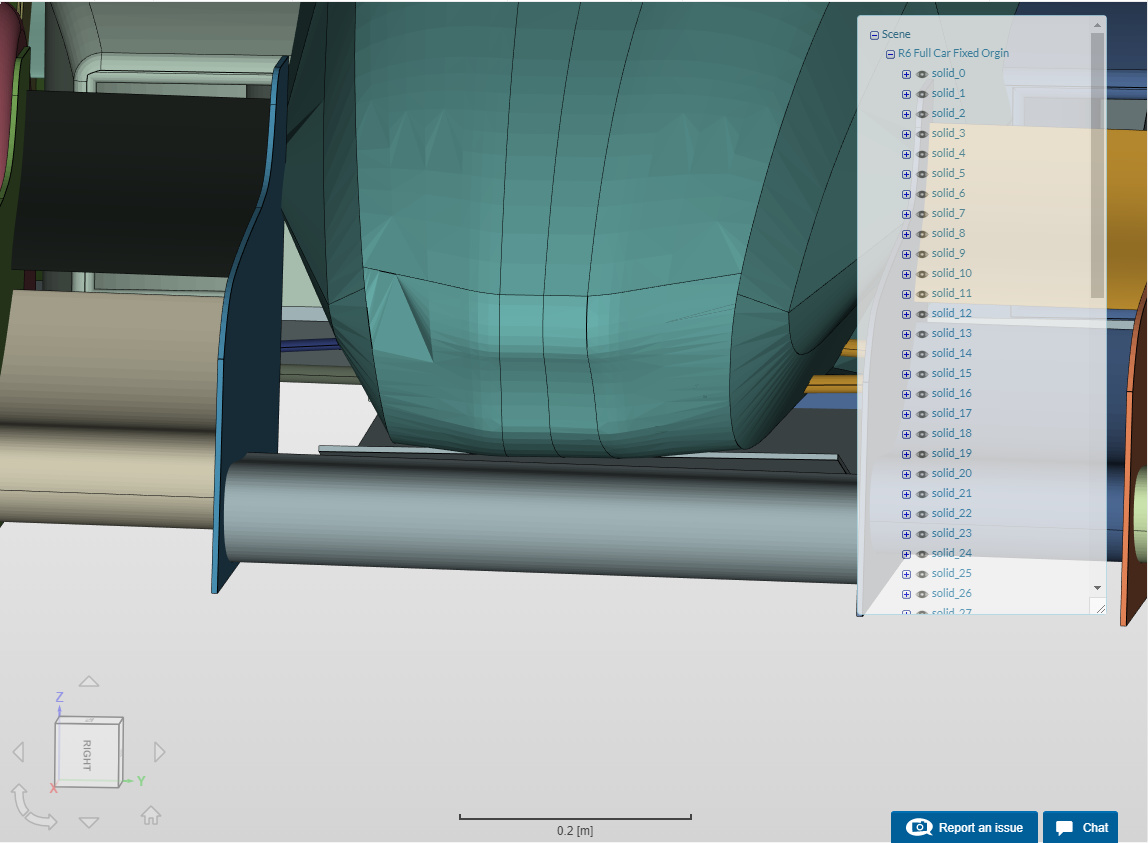
I am confused where I have open spots in the model, in Solidworks the whole model is all solids. I think I may have an issue with how my file is being exported from CAD or imported into SimScale platform. When the model gets imported into SimScale, it adds “faces” for each side, and then turn the model into a hollow model when a mesh is created.
How do I fix this?
Would you like me to share the Solidworks Assembly with you?
Although you use solids it can still be that there are holes inside the geometries causing this issue. Just to make clear what watertightness means here a good post by @dheiny: SnappyHexMesh - Watertightness. Make sure that the inside of the geometry can not be “flooded” if you wanna put it like that.
Thank you for your quick reply.
That post did help clear that up, however that still doesn’t explain why the geometry is getting “eaten” up when meshed. Unless my material paint could be messing it up?
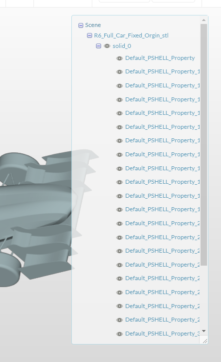
If I export my model as a different format it will import into SimScale only as “Solid 0” with no faces attached or anything, however if I use an IGES I get faces in SimScale.
The information with the material point was just a side note - this determines if you are performing an external or internal flow analysis. Having a single solid won’t help you much as you will run into trouble with boundary layer creation for your vehicle so splitting the surfaces will be an essential part of the pre-processing.
The only issue though is that in my case some of the PIDs merged (maybe when importing the CAD due to similar names) and I didn’t realize 'till I was setting up the simulation. But that’s something I could fix easily.
In short: try converting your CAD into STL and upload that instead of a STEP file.
I know that when I was trying to upload as a STL, the online platform was never able to process my file. Maybe there is something messed up with my version of Solidworks. I’ll have to try exporting on a school computer. Did you convert it in SimScale or using a CAD program?
I guess you can use your own CAD software to do the conversion. As per the format, there are to possibilities: ASCII and binary. The former is human readable so to speak, while the latter is binary data only readable by computers. Might be binary is OK; but I usually had less issues with ASCII.
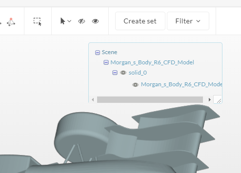
So it turns out I was actually wrong. That did not fix my issue. I had downloaded your STL and accidentally uploaded that when I was trying to test mine.
Now my problem is how the platform is importing the STL. With your STL I could select individual assemblies (rear wing, front wing…) When I create one the whole assembly turns into one part.