I saw this subject already in the forum a few times, but have not been able to resolve things. So I hope some one can help. It is about my project:
Simulation: Incompressible 6
Run 3 is using Realized k-epsilon and Run 4 is using k-omega SST.
Both have this ‘Gauge pressure field started diverging’; Run 3: at Gauge pressure = -1.04349e+15 at position: (-54.24 m, -76.35 m, 0.5804 m).
and Run 4 at: Gauge pressure = 1.41853e+15 at position: (-86.87 m, -46.04 m, 0.5278 m).
I get these errors also when changing the Mesh Fineness at 5, 7.5 or 9.
<the model worked (although I had a smaller height for ‘External Flow Volume’: in Simulation Imcompressible 6 it is 100m, while earlier [in Simulation: Realizable 225deg (7.09m/sec,terrain=10m)] it is 40m>
If I look at the Mesh I am not really able to see any strange things. But sometimes I get or a blue field or sometimes nothing, So it looks I don’t know how to debug this.
I wanted to set a point (like advised in: Divergence in Simulation: How to Tell When and Where? | SimScale ) but I can’t find this option: ‘Geometry primitives’.
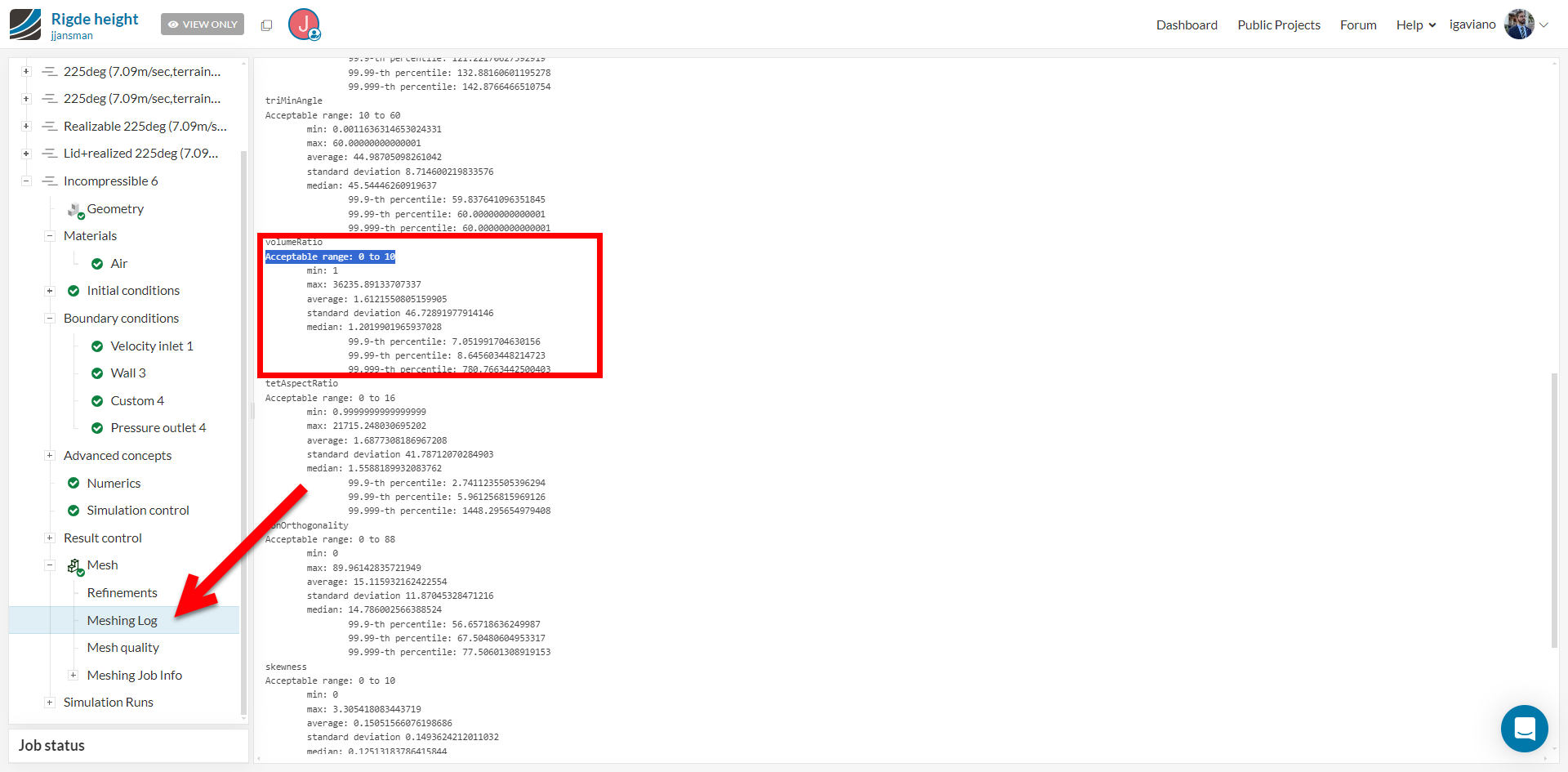
The Mesh runs by the way gives this:
“The model contains faceted geometry. When Advanced concepts are used, the meshing pre-processing requires some boolean operations to be performed. The support for facet geometry is limited in this case.
This mesh meets our quality criteria.”
Hello @jjansman , I hope you’re well and apologies for the delayed reply here.
I have noticed nothing unusual in terms of boundary conditions, however noticed there are some mesh cells that are beyond the acceptable quality range.
I would recommend having a mesh quality check first. Depending on the reasons, you can either apply mesh refinements to improve the quality, or you may need to perform cad clean-up operations. Please make sure that you’re referring to the following documentation page:
I will have a check. And see if I can find these areas. Would you be able to show (in a grab) where “some mesh cells that are beyond the acceptable quality range.” perhaps I am overlooking this when checking the mesh quality? THANKS.
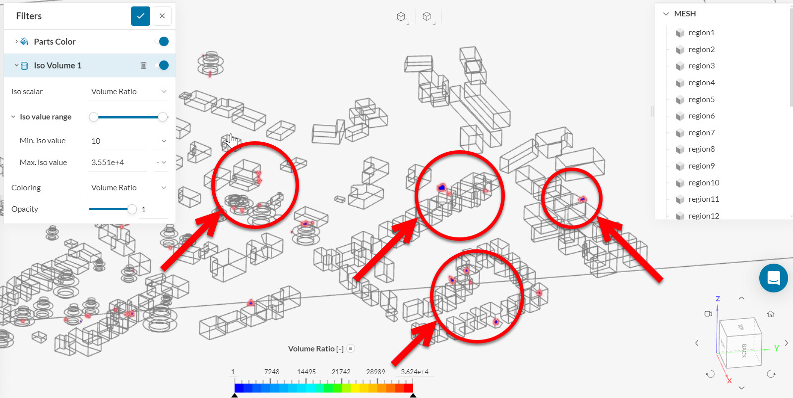
This indeed helps!!! Now I see what to look for, it seems I had the min at a wrong value. I tried first 40 very thing becomes blue, then I used 50 and 60 that locates one locations. But changing it to 10 (as you did) I see more, Is ‘ideal min’ indeed the dieal? In the workflow I say 20 (which only shows one location).
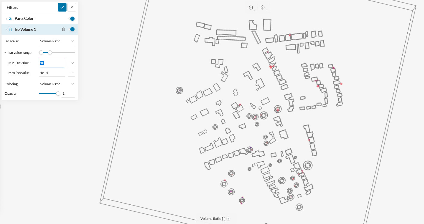
it seems also I need to be patient;-) After change the min, it takes some time and then I get a blue space after some time, the blue is removed and I see one colored space:
Do I now need to change all locations where things are lighted in when using min=10 or could I start with the location that pops up at min-20 (or min-70) An
Anyway THANKS for being patient with me. At least I now can reproduce the things you see and thus I hope to be able to improve things. THANKS.
All the best,
Victor
I now checked Aspect ratio, Non-orthogonality, Volume ratio, Edge ratio, Cell volume and non of these show issues in the Mesh Quality at the locations mentioned in the Runs:
Run 3: at Gauge pressure = -1.04349e+15 at position: (-54.24 m, -76.35 m, 0.5804 m).
and Run 4 at: Gauge pressure = 1.41853e+15 at position: (-86.87 m, -46.04 m, 0.5278 m).
I was not able to find ‘Geometry primitives’ option to locate these points, so at the end I looked at an earlier successful run with the same model and with x, y, z (in Solution Fields) I found the locations. As said no issues were seen there in the Mesh quality view.
At the end I reduced the Roughness height of Custom (from 10m to 1m) and now I can Run it successfully. If I try Roughness heights 3, 5 or10m they all cause errors in run (I did not try 2 yet).
So I did not yet find a useful workflow to get it working.
I now got it working. I had not done Initial conidtions and enabling potential flow initialisation. And furthermore (perhaps the bigger error): I had no Inflate boundary layer (in the Mesh) for ground level (only Boundary conditions, but that is not enough).
When including these in the simulation, I get no Gauge pressure field started diverging anymore.