Hello Support,
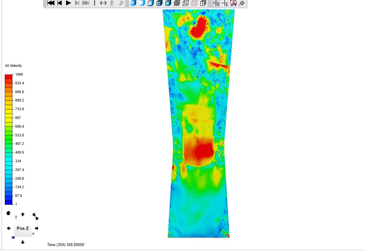
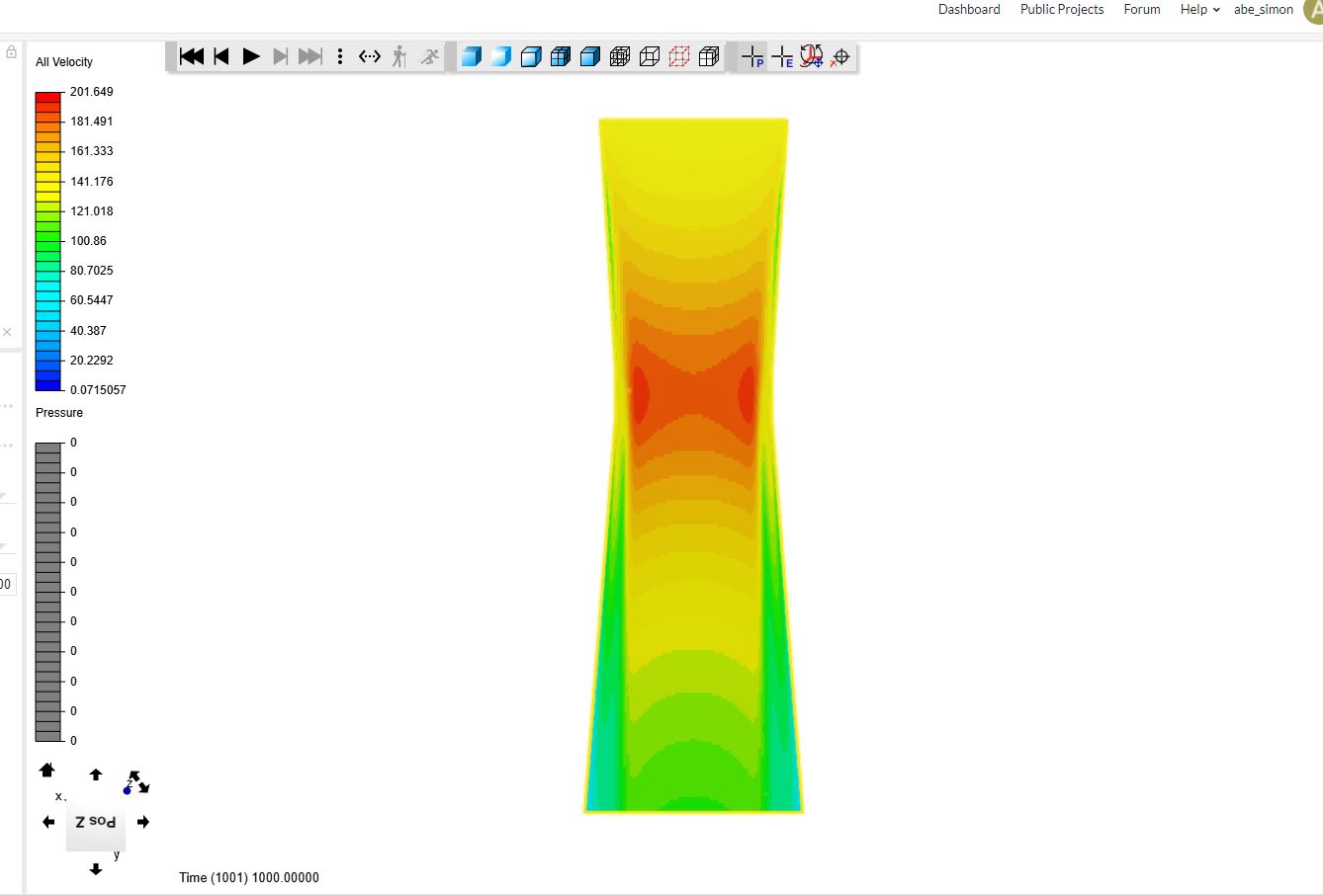
I am trying to simulate flow through a 20mm intake restrictor using the compressible analysis feature. I have my boundary conditions set up with an ambient pressure inlet (101325Pa) and a mass flow rate of (- .0703 kg/s which is the theoretical mass flow rate through a 20mm orifice). I set the mass flow rate to negative since it is leaving the boundary. I’ve tried it with a positive value, but looking at the post processing in ParaView, the flow seemed to loop around and do some pretty whacky stuff. Overall my goal is to look at pressure drop across the restrictor for two different designs to come to a final decision. I can’t seem to get reasonable post results, using compressible flow, there are lots of areas with super high velocity where it should be fairly uniform for that cross section. However, using incompressible flow, I can get a very smooth pressure cutting plane I just don’t know if the results are reasonable based on the characteristics of the air restrictor. Any ideas on how I can change my compressible flow numerics or settings to produce an accurate representation? Also, would there be an easy way to measure pressure difference between the inlet and outlet? I know this is a long post but any help would be hugely appreciated! Thanks.
1 Like
Hi @abe_simon!
Which restrictor project do you mean? You have two as far as I can see. Also do you have a paper as a reference where can have a look at the expected results or is this something you are trying to find out by yourself? Compressible flows are quite tricky as my colleague @Get_Barried already stated in his recent posts. Also we cannot give you a basic recipe on how to treat compressible flows as small numerical settings can have a big impact on your results - so that’s why I was asking about the paper  If there’s anything you would like to share with us, please do so and also post the project link.
Cheers and thanks!
Jousef
1 Like
Hi @abe_simon,
Do post a link to your project so it will be easy for people to access your project and help! On top of this, do be specific on what particular simulation you are having problems with.
On to the problem. Coincidentally enough, I am in the midst of performing a compressible simulation myself! So I may not be able to provide you with a definitive solution, but I have some general ideas.
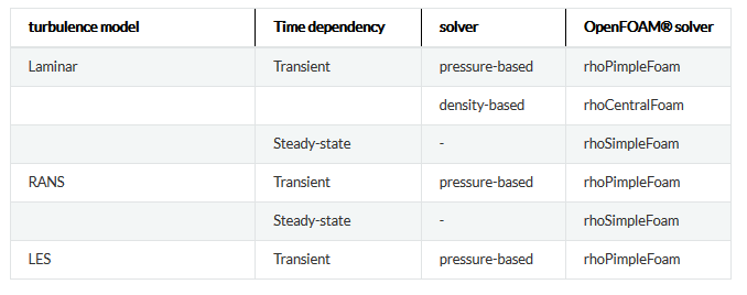
I’ll be referring to this simulation. Firstly, your analysis type is likely incorrect. Currently, you have used both the compressible k-w SST steady-state and laminar steady-state analysis types. Both of which use the OpenFOAM utility rhoSimpleFoam. rhoSimplefoam has problems when it comes to transonic and supersonic flow as it is unable to resolve the shockwaves within the flow. So that leads to my first question, what is your Mach number? I assume it would not be lower than 0.3 as compressible effects are negligible below that.
I recommend instead using rhoCentralFoam which is the laminar transient analysis type. This is better able to capture the shockwaves and transonic/supersonic flow as it has additional equations coupled to formulate the presence of such effects. Since this is a transient analysis, it will be more costly computationally and you will need to calculate out your Courant number which will give you your timestep. Keep in mind that you need to ensure that your end time is the time taken for flow to progress through the whole geometry. For example, if your tube is 1m long and flow travels at 1m/s, then your end time needs to be 1s. Keep the numerics at default and everything to first order implicit (euler, gauss linear, no leastsqr).
Here comes the tricky bit and one I have not personally resolved myself, the Boundary Conditions. For your case, I see that you have deduced your mass flow rate and that is a good step forward. I suggest setting your geometry as a slip-wall first in order to reduce any potential problems as we need to ensure the inlet and outlet assignments are correct. For the outlet, set is as custom and all parameters to zero gradient. We don’t want to force the solution out as not only will this restrict the behavior of the flow giving erroneous results, but you may also hit continuity errors. For the inlet, you can try setting it as custom as well but define the velocity as a mass flow rate, similar to what you have done now. Pressure should be set as Total Pressure and leave it at gauge pressure first (101325, same as your initial condition). Temperature can be set to a fixed value of whatever your initial condition is.
Note that my suggestions are just guesses at the moment and we will likely run into problems. So do let me know how the simulation behaves and we can continue to work on it as I am also very interested in resolving this problem.
Cheers.
Regards,
Barry
2 Likes