“However beautiful the strategy, you should occasionally look at the results.” - Winston Churchill
Thus results are one of the most important part of any simulation. One can’t simply accomplish his/her simulation mission without properly post-processing the results. Therefore, this post shows how to post-process the solid mechanics simulation results using both the online post-processor and local ParaView. So let’s get in to it!
Similarities between both post-processors
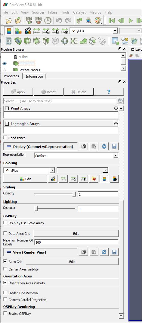
Before we start, let’s have a look at the similarities between both post-processors. Since the online post-processor uses ParaView in the background, therefore there are many similarities between the two. The figure below shows these similarities with description.
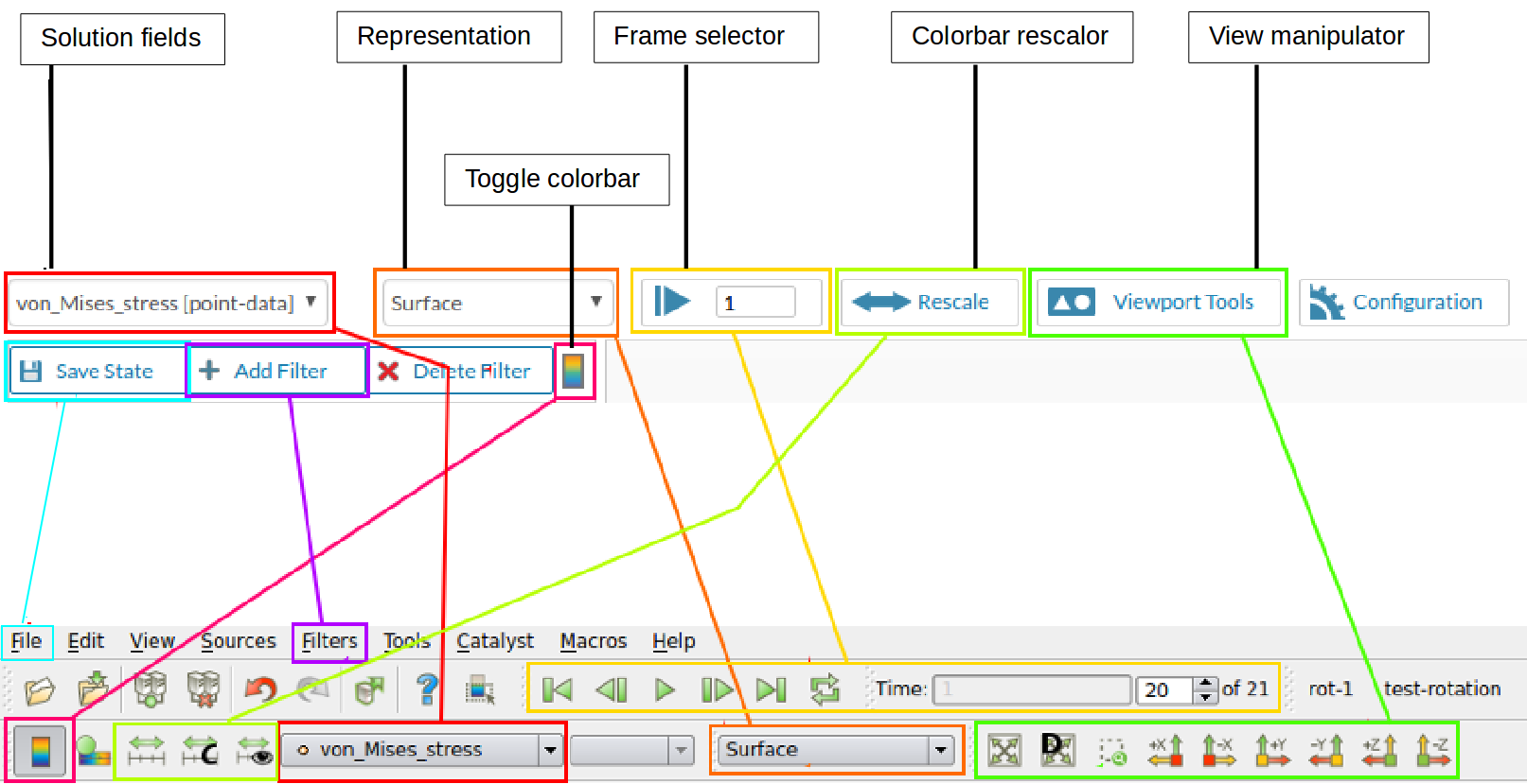
Similarities between the online post-processor (top) and local ParaView (bottom)
We now elaborate each option according to the highlighted color:
Red: Here you can select between different solution fields e.g. von Mises stress, displacement, temperature etc. The number of available fields depend on the requested solution fields under Result Control in simulation setup
Orange: You can change how your model under viewer should look like e.g. surfaces, surfaces with edges etc.
Yellow: You can select a specific timestep frame of your simulation. This option will only have multiple steps in case of static nonlinear or dynamic analysis.
Light green: You can rescale the color bar to your need. For example, you can rescale your vonMises stress from 0 to 1e7.
Green: You can use these tools to change the view of your model in viewer.
Blue: You can save the state of your post-processor so that you don’t have to reapply all the settings when reopen the post processor next time. For local ParaView, you can save the state by going to File and then clicking Save state. to reload the state in ParaView next time, just go to File and then click Load state and select the saved state to load it.
Purple: You can add different filters based on your requirement. In local ParaView, under Filters you can either look for the filters arranged according to their type or directly search for one by using Search option.
Pink: You can toggle on or off the color bar (legend) which shows the value range of your selected solution field.
When to use online post-processor and local ParaView
If you want to have post-process results quickly, use online post-processor. On the other hand, if you want to post-process the results and apply some special filters to get much better looking results, use local ParaView. In some cases if your mesh is big and you have low memory available on your PC, using online post-processor is recommended.
Loading results in local ParaView
Loading results in local ParaView is not as simple as in online post-processor that you click the Solution field of the results and it automatically loads it in viewer.
In order to do it, please follow the documentation here: Post-Processing via 3rd-party Solution
For structural mechanics simulation, the file with either name case.pvd or sim_0.vtm needs to be loaded.
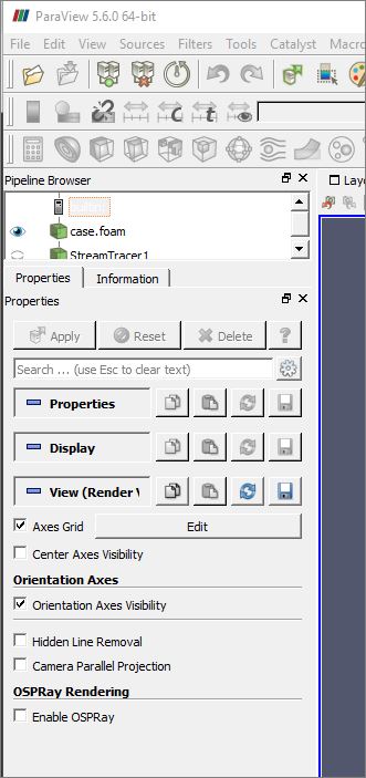
Making local ParaView to look similar as online post-processor
There are some differences initially between online post-processor and local ParaView. To make them consistent, please do the following:
Before doing these changes, make sure that you have opened the result file in local ParaView and have clicked the Apply button. Otherwise you would not be able to follow the steps provided below.
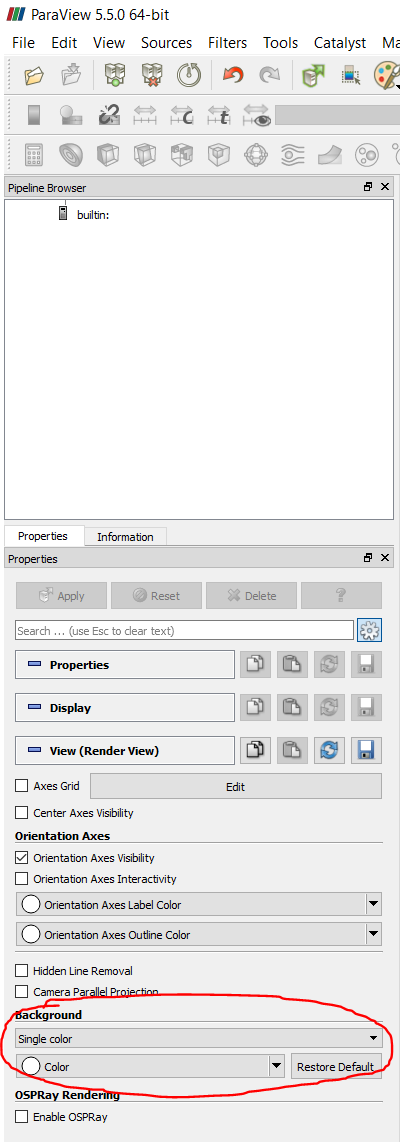
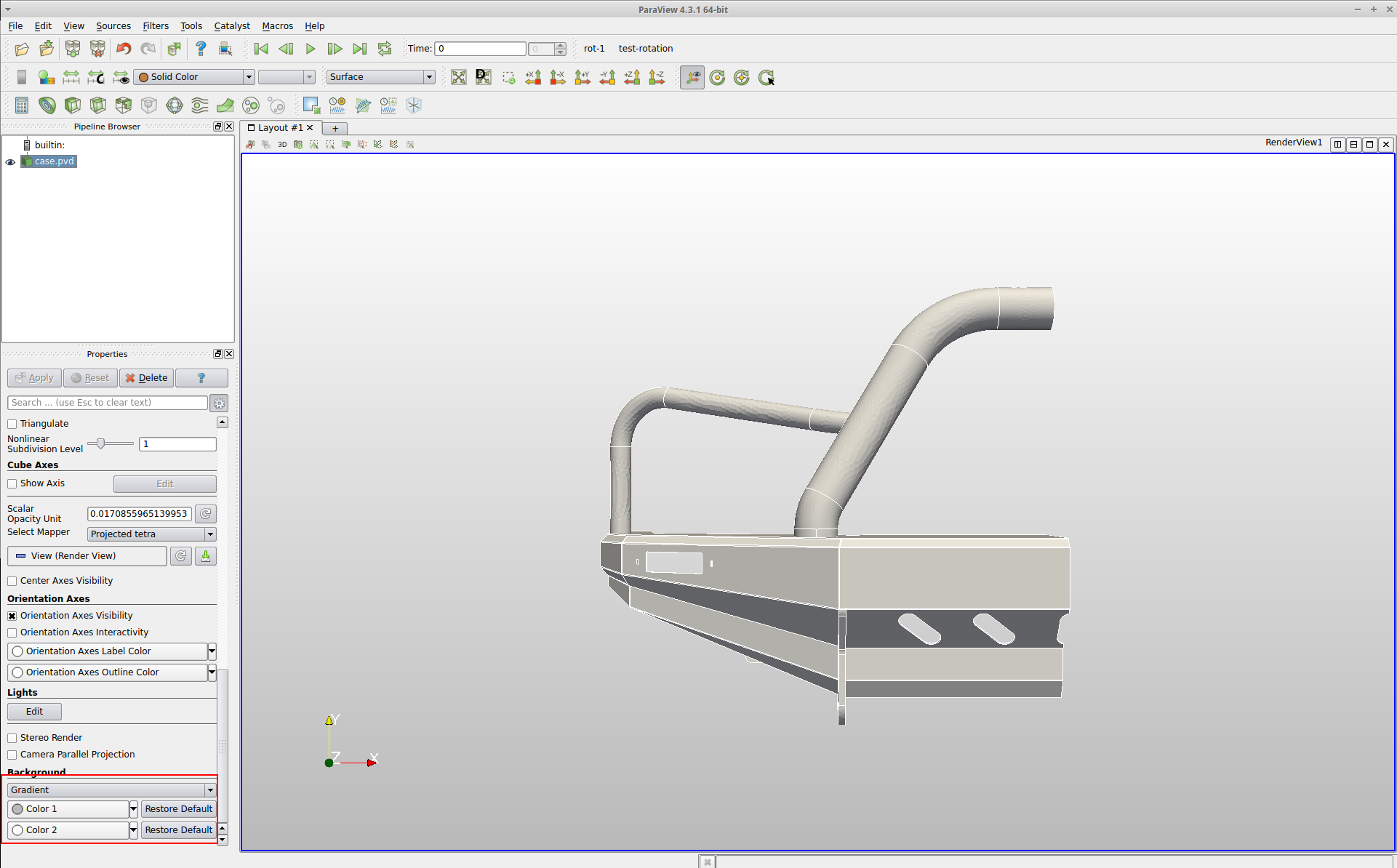
Background: The background of the local ParaView is always different than the online one. To make it similar, scroll down to the end in the properties panel and change the Background from Single color to Gradient. Click Color 1 and change Red, Green and Blue to 185. Click Color 2 and change Red, Green and Blue to 255.
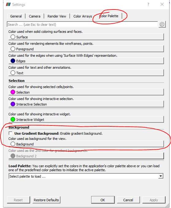
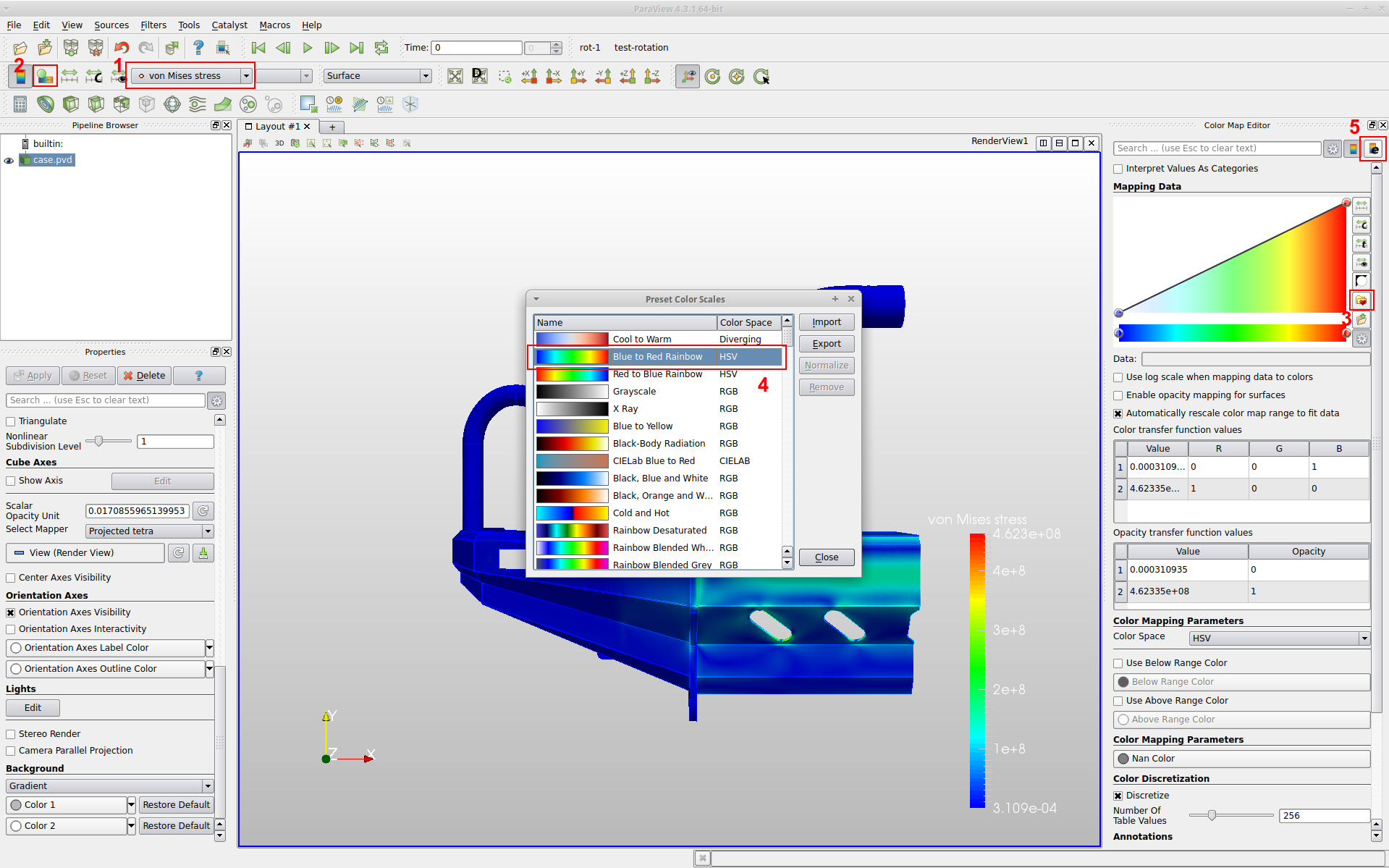
Color map (bar) preset: To change the color bar to the same preset as in online post-processor, do the following:
- Make sure you have selected a desired solution field whose color map (bar) preset needs to be changed.
- Click Edit color map button which will open an edit panel on the right.
- Click Choose preset button to open a new popup window.
- Choose the second preset i.e. Blue to Red Rainbow.
- In order to change the text color of the legend, click Edit color legend properties button.
You have to change the preset color for all other required solution fields by following the same procedure.
Now you have learned the basics and also how to setup the local ParaView for post-processing, let’s jump in to our first example.
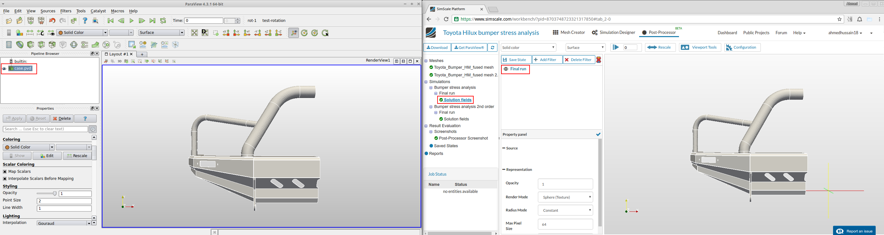
The post-processing is performed in parallel with local ParaView on the left and online post-processor on the right.
Single step static analysis example
The test case used in this example can be find here: Toyota Hilux bumper stress analysis
Step-1: Load the results in both post-processors.
Step-2: Due to symmetry, only half of the model was taken for analysis. In order to make it full, we have to reflect (mirror) the model along symmetry plane. This can be done by using Reflect filter.
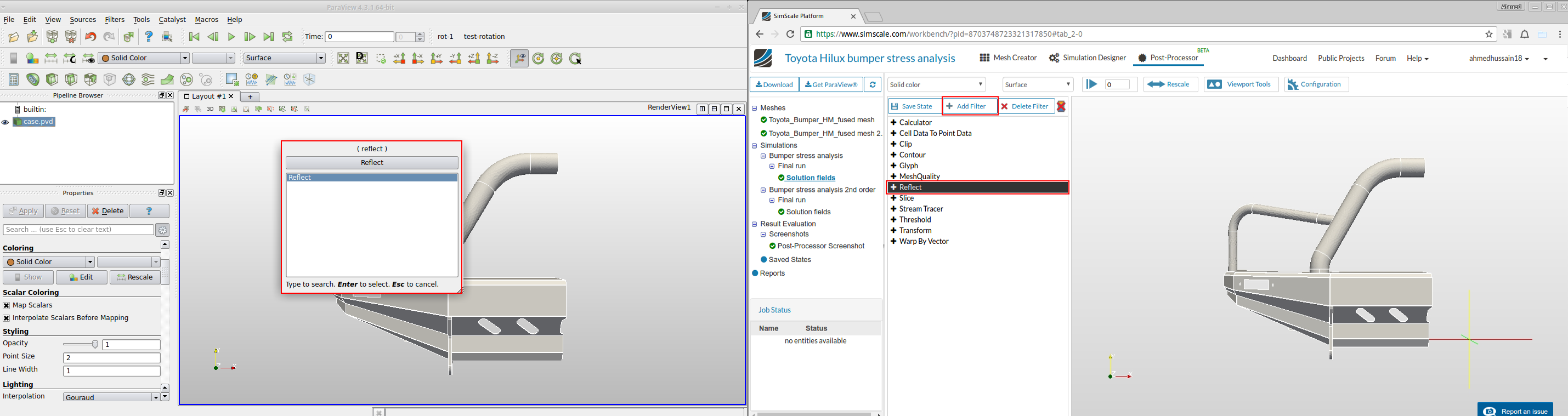
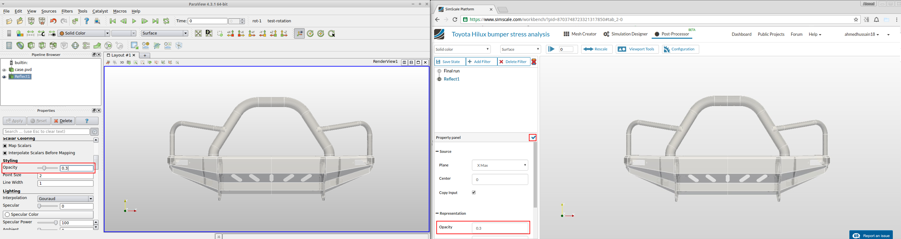
Step-3: To reflect this geometry, change Plane to X Max and then click Apply. (you have to turn off the Final run visibility by clicking the eye on it’s left)

In order to turn off the visibility of center of rotation lines in online post-processor, click  under Viewport Tools. Furthermore, to enlarge the viewer you can close the side tree panel by sliding the panel bar to the left.
Step-4: This is now our initial state of our geometry. To make it transparent, change the Opacity level to 0.3 under properties panel. (you have to click the tick button to apply this in online post-processor)
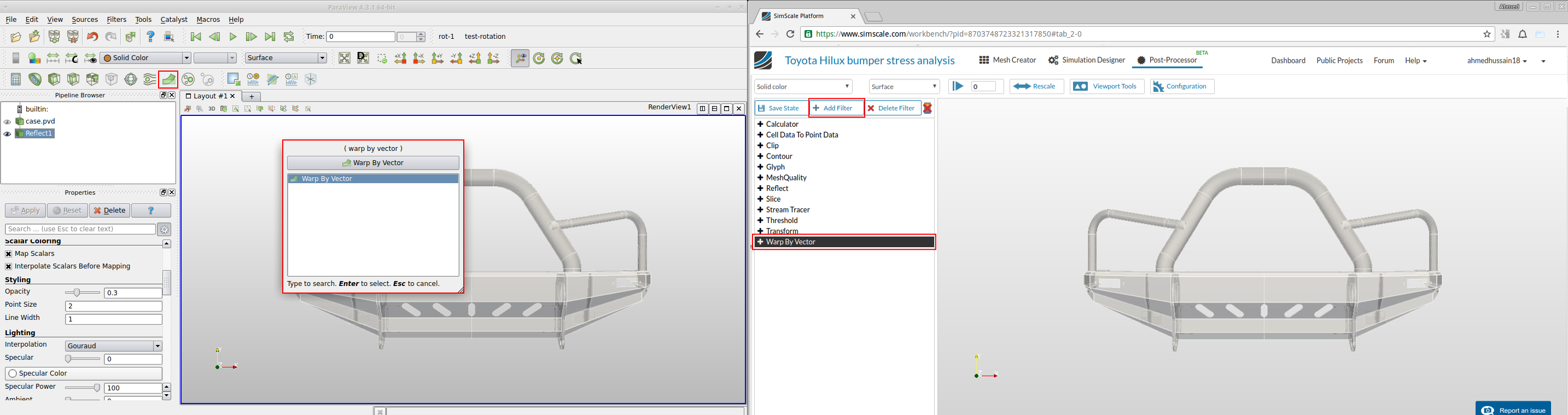
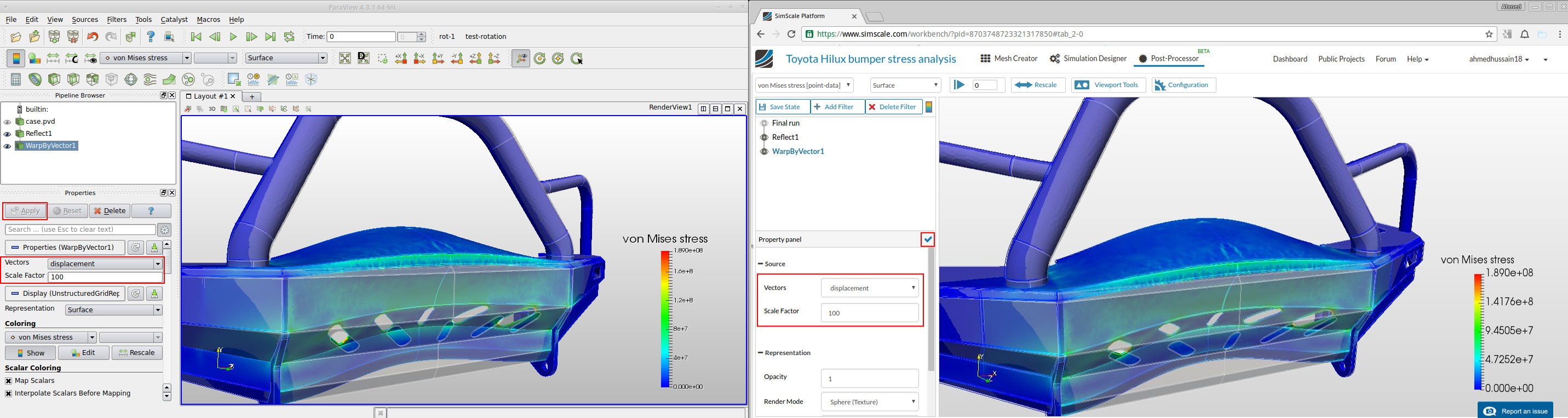
Step-5: Now to see the deformed shape of the geometry, select the Warp By Vector filter under filters. Make sure Vectors is set to displacement and then click apply. (you have to turn on the Reflect filter in local ParaView by clicking eye on it’s left)
Step-6: Apply the desired solution field to this filter e.g. von Mises stress in this case. Make sure the color bar is turned on. If your values of legend in local ParaView is not same as online one, click rescale button highlighted in blue.
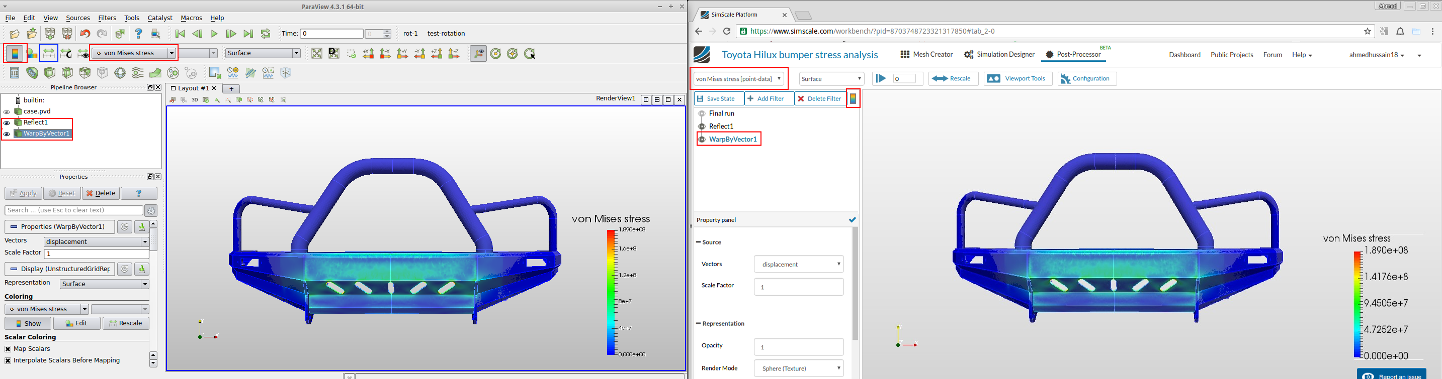
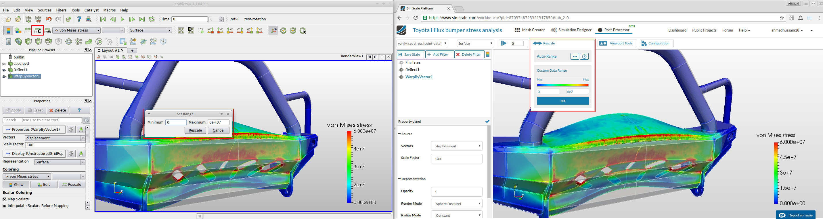
Step-7: In order to enhance the geometry deformation, increase the Scale factor to 100 and then click apply. You will see that now the deformed state is scaled 100 times.
Step-8: Next we can rescale the legend values to our need. For local Paraview, click Rescale to custom data range button to rescale it. On online post-processor use rescale to do so. The rescaled stresses are shown in the background.
Step-9: In order to save the screenshot, click save screenshot button under Viewport Tools for online post-processor and File > Save Screenshot for local ParaView. The saved screenshot will appear under Screenshots in left tree.
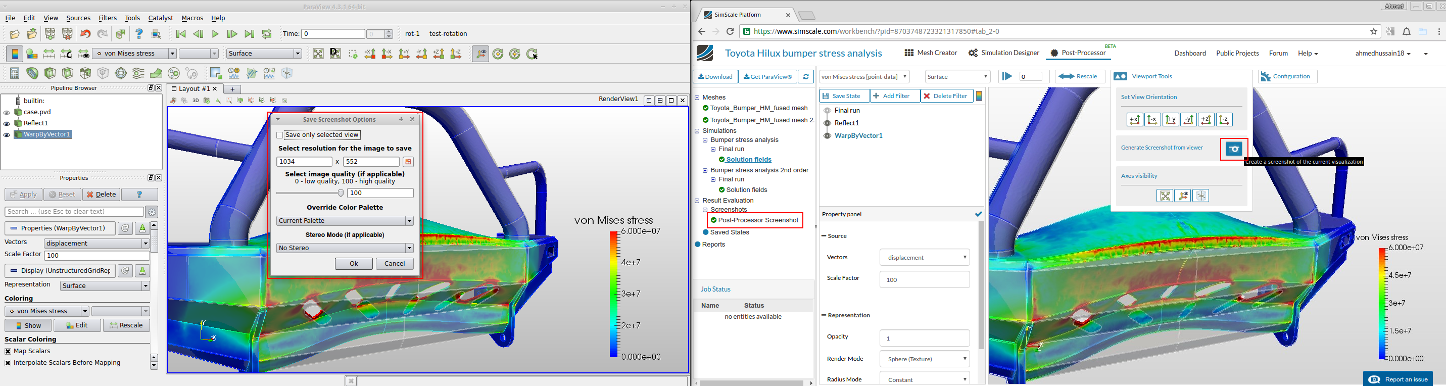
You can save your current state by by clicking the Save State button in online post-processor and by going to File > Save State in local Paraview. Saving state will help you to continue from the same point later on or to load the state next time you need it
As a second example for post-processing multiple step nonlinear static or dynamic simulation, please follow the tutorial here.