I’m trying to make a CFD simulation of building air inlets and outlets depending of the outside wind speed and direction.
In “Boundary conditions” I set the doors on the left and the right sides of the buildings to have air intake, a on the sides of the buildings are windows with warm air outlets.
I’m curious to see, if warmer air from the windows will go back to the air intake doors, but I have a problem with the start of the simulation. I’m getting “An error occurred.” message every time.
The configuration was made from the similar projects that I found in Public projects, but I can’t get mine to run.
Hi @mpilas and thanks for your detailed description.
The boundary conditions definitely mess with the simulation and cause it to fail. Will have a look at it later on and let you know how you can optimize it. @cfd_squad might as well jump in in the meantime.
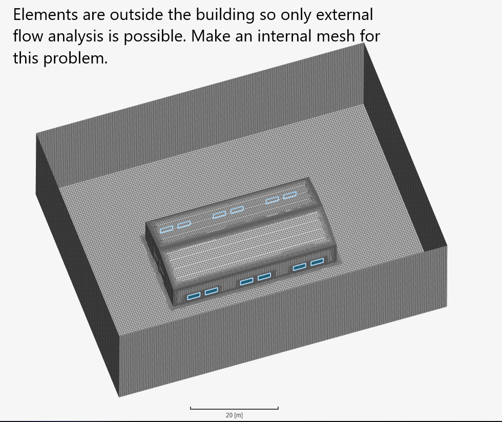
The mesh created by you will only let you do an external simulation of this building and an internal flow analysis is not possible as there are no element inside the house. You should make an internal mesh for this problem.
I will take a look at this in a bit when I get back to a computer. It sounds like you may need to use Inlet/Outlet boundaries for part of your problem or maybe even connected face sets.
I think you just need to use external CFD with the CAD model of a hollowed out building but with solid walls 6 or 8 inches thick or whatever. Even include internal walls and doors etc…
But sir looking at the faces where he has assigned the inlet velocity boundary condition, don’t you think he is trying to analyse the flow inside the building(rather than outside).
Maybe but I sort of got the feeling he wanted to see the flow through the building with doors and windows open, I could be wrong but now all the options are there
Not quite sure how often a wind would come from both left and right side though, perhaps as a thermal passes through
EDIT: Yes of course my brain saw that air would go in the right doors with a wind from left since it sees those pressure plots without CFD but my words failed my brain here
actually, that is my attention. I would like to see the behaviour of external air flows and temperature around the building. So I need to do an external simulation, not through the building.
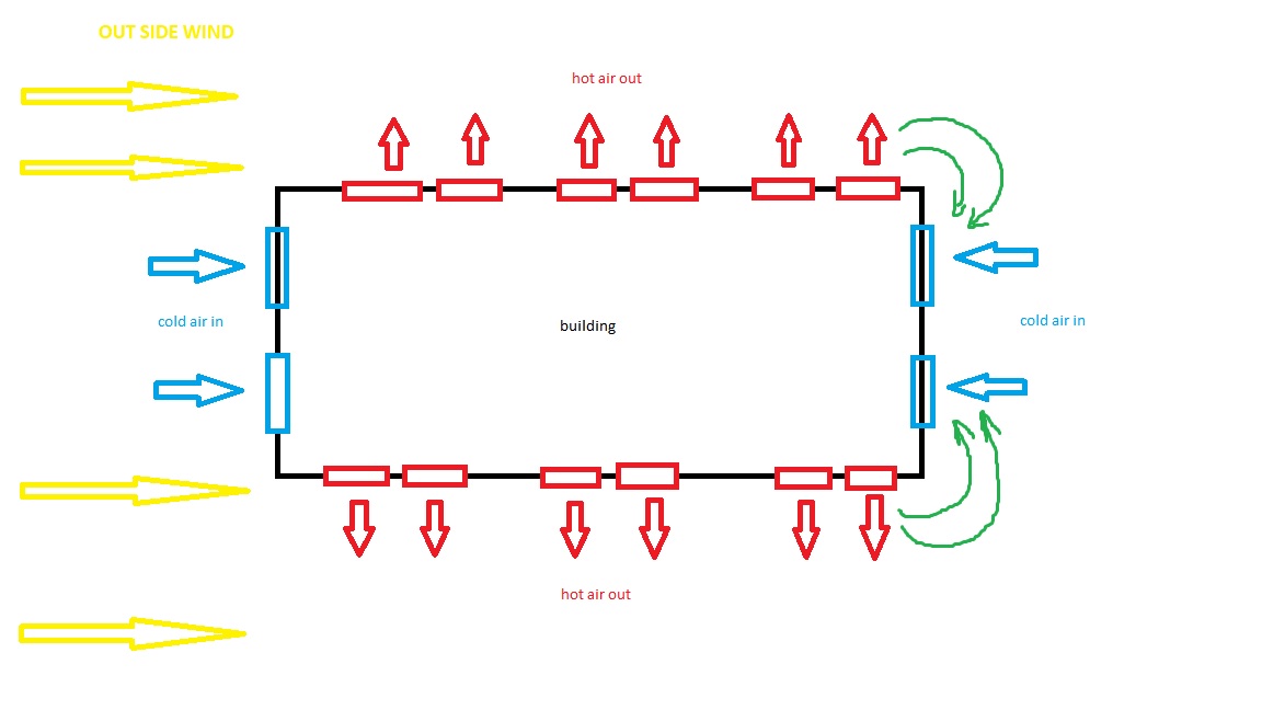
Let me explain the situation a little bit more. Eight doors from the (left and right) are taking cold air from the outside into the building. Inside the building, there is a manufacturing process which is generating some amount of warm air, which is going out through the six windows on each side of the building.
I would like to see will wind from the outside of the building on X and Y axes (let’s say from the southwest) push warm air around the building back to the intake doors. Later in the simulation, I would like to change wind directions and velocity also with air temperature that is going out through the windows.
Thank you all for your help, and sorry if I didn’t clarify my situation in the beginning.
So, I think you need to model the building as I suggested and make sure you model the indoor walls and doors and even the equipment if it is large…
I think you need to add the heat source in a sim … Others can comment on inlet/outlets with likely zero gradient walls too for this projects Background Mesh box.
I would do it as one watertight solid with a floor and have equipment attached to floor too.
Get a good CAD that people here can comment on before you try a sim…
There is a lot to unpack here. I would start with a simple simulation of just the building with an inflow through one set of doors and the windows/other doors set as pressure outlets. You can change the direction of the inflow by changing the velocity on the face. @DaleKramer is correct that you will probably have to model a bunch of the equipment if you actually want to get heat flow. That could be a very daunting task. Still, I would start with just an empty building and the inlet/outlet I mentioned above.
The idea is to keep this as simple as possible. I know the measurements of the air speed at the doors, and I know what is the airflow and temperature of the air that is going through windows.
I was thinking it would be possible to simulate my problem with the above data.
In your scenario, are both sets of doors and all the windows open at all times or are you looking at a situation where the doors open and shut but the windows are always open? This will make a huge difference in how the simulation is setup and what type of flow phenomenon you might see.
@LWhitson2 in the first scenario, I would like to see a situation where doors and windows are open. In the second scenario, I would like to “close” one set of the doors, or one set of windows located near to the doors to eliminate warm air mixing with the cold air and going back into the building.
If this data of yours is truly accurate and represents an even flow across the complete window/door panes in a 7 m/s domain inlet wind (unlikely), then the flow pattern you see might have some validity.
Personally I would like to see a better sim setup that might validate your numbers by simply CADing the interior, remove the window and door in/out boundary conditions and then really see what CFD can do
@mpilas I set up a simple simulation like what we are talking about for you. You really need to model the interior of the building with the equipment generating heat. Once you get the simulation complete I think you will find there is very little recirculation back into the building. Below is a link to my project and a quick clip I made. Keep in mind, this is nowhere near “correct” or ready, just a demonstration. You need to get proper heat generation for all the equipment and a much better grid.
@LWhitson2 thank you so much for your simulation. It will help me a lot to learn how to better prepare simulations in the future. I made a lot of mistakes in object preparation.
Eventually, I got what I was looking for. It is a very rough result, but it will help me to learn since this is a learning “project” for me to understand how Simscale works and what are the possibilities. I didn’t have any 3D CAD or CFD experience before this.
To clarify, I know what is the temperature of the air coming out of the building since there are sensors installed on every window.
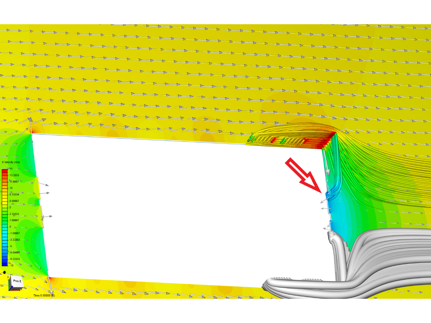
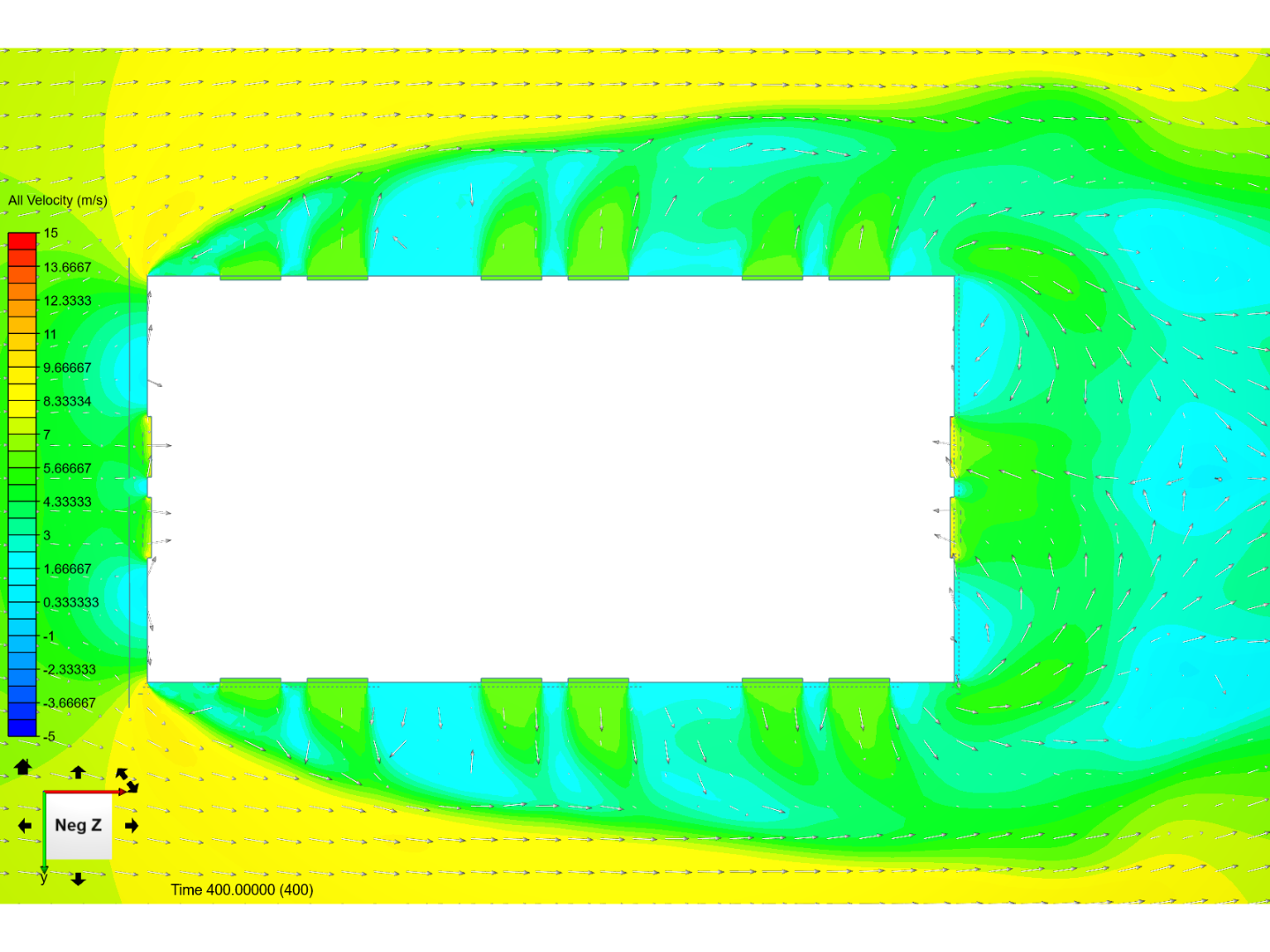
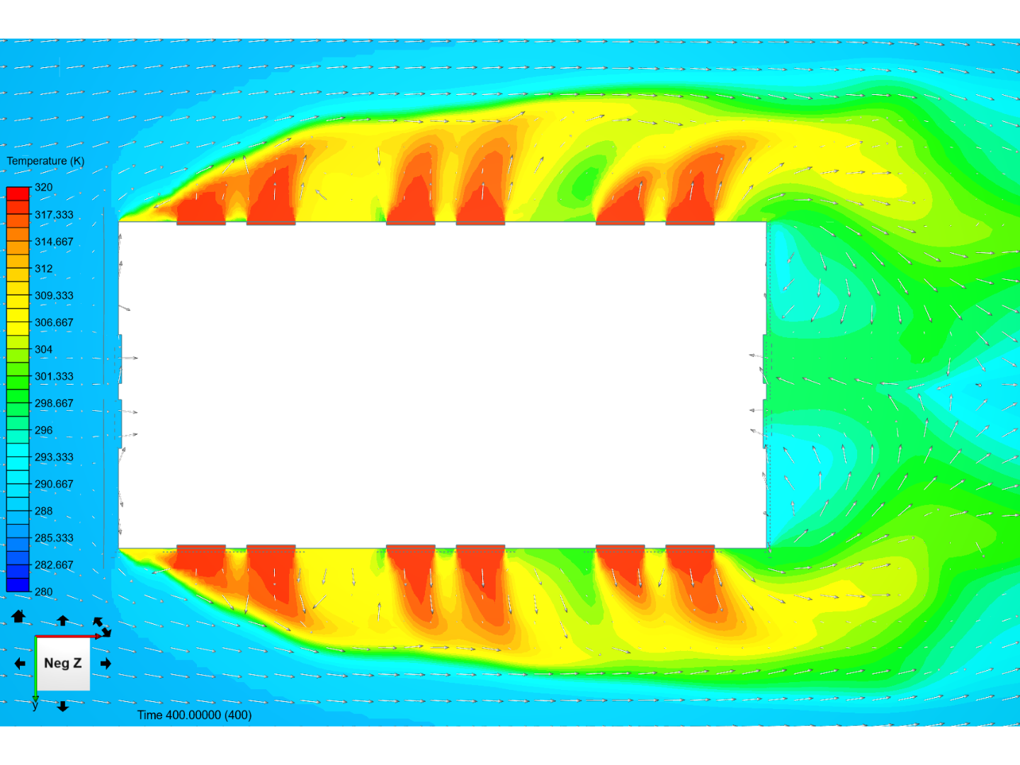
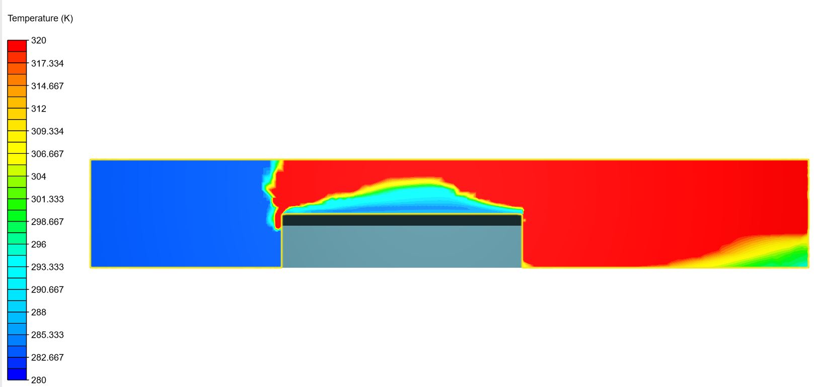
Hi folks, I noticed something interesting while doing this project, and I’m not sure why is this happening. When I look at simulation results, I noticed that hot air is accumulating around the building. I assumed that hot air will go away, but it is staying inside of the geometry as shown in the pictures (this strong red part):
I have set the right side (last picture) to be a pressure outlet with 0 Pa, but it seems that hot air is not going out. Instead, it is accumulating and going up to fill up the whole space with the hot air.
What would be the right setting for this situation to simulate endless space with free moving air going out of the geometry?
Hi @Retsam, thank you for your input. I tried your suggestion with setting 3 faces to custom and one face as pressure outlet (side walls and roof) of outer geometry. With that setting I got an error after a few minutes of running simulation:
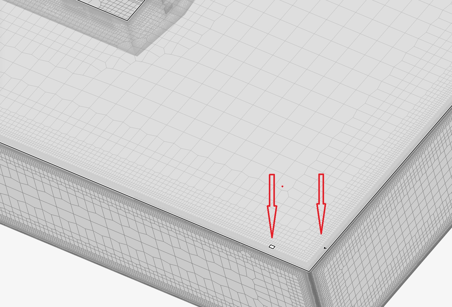
“The solution diverged, most likely due to presence of bad elements in the mesh. Such elements tend to exist near walls and sharp corners. Visually inspect your mesh to locate them and re-mesh with additional refinements in their vicinity. If you are confident about the mesh-quality, please reduce relaxation factors and use more conservative numerical schemes.”
I assumed that the problem is caused by these holes in the mesh:
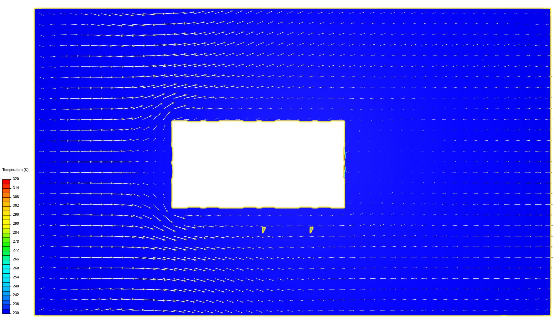
But I also run one more simulation with 4 faces with a custom setting without pressure outlet face. This simulation finished ok but the results are not correct. Simulation fields are not showing temperature air that is going out from the windows.