Hello everyone!
I’m quite stressed as some of these simulations have to be finished as quickly as possible. Whenever I did simulations prior to these, I never encountered this Error:
“Velocity field started diverging. Please check the mesh quality near the reported location and try refining the mesh. If the problem occured near a boundary, please check the boundary conditions. In case of doubt, please ask for assistance via our support chat.”.
Could someone tell me what is causing the error and how we would be able to fix it?
It happened in these simulations:
Whereas it didn’t (yet) happen in these:
Also: the simulations are from a different account as a member of my team did them on his.
I quickly scanned the 1st project from each list to spot any differences in the setup or for any issues.
It looks like, in terms of the simulation setup within the boundary conditions, everything looks fairly good.
However, the current mesh quality indicates many poor quality mesh elements between the wheels and the ground. You can investigate the mesh quality visually based on several characteristics using the mesh quality visualization tool and following along the page here:
The geometries used seem to be slightly different, hence why the simulation progress may differ. However, I do not expect these generated meshes with the current quality metrics to lead to reliable/consistent simulation solutions.
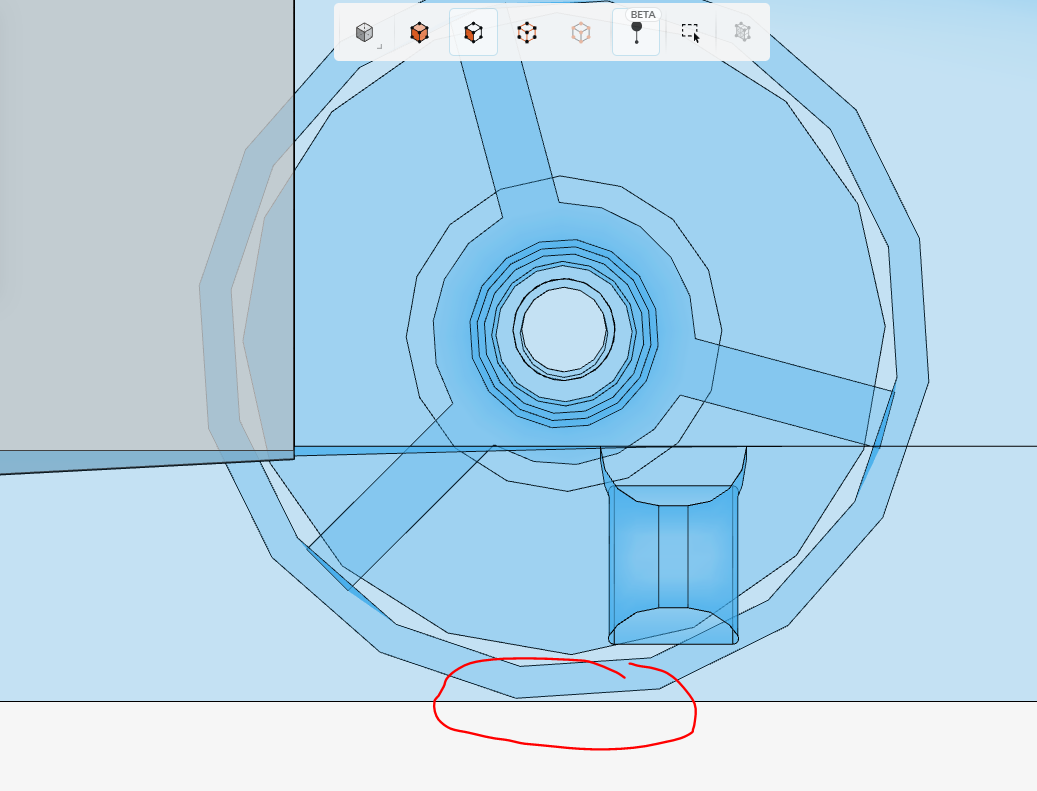
I’ve attached a screenshot of the problematic area (applies to both wheels); I’m visualizing where the mesh element aspect ratio is above the ideal maximum of 100 (reaching up to ~852), but other metrics like the non-orthogonality being near or above 88 is another metric for mesh quality.
Normally, the recommendation would be to refine the mesh in these areas, however, your geometry shouldn’t even have a flow gap between the wheels and the ground. I’d mitigate this issue first, then when generating a mesh, applying similar refinements as you’ve already done will be a good start to generating a good quality mesh early on.
Creating multiple meshes in parallel (highlighted here: Meshing in SimScale | Simulation Setup | SimScale) can help speed up your workflow, but be sure to give each mesh a descriptive name so you are aware of the changes you’ve made and that way you’re consistent.
I hope this helps! Let me know–is this for a Student Formula SAE project or other work?
Thanks for your answer! Since the wheel doesn’t look totally round in SimScale, should I align the lowest point of the wheel with the floor of the flow region?
The competition is about miniature cars (f1inschools).
Exactly! Essentially, you don’t want any portion of the flow domain body to be below the wheel, as the wheel and the ground are in contact.
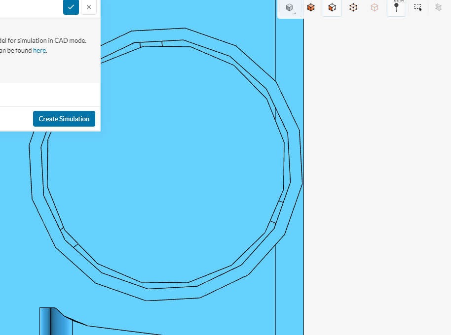
However, depending on your CAD tool’s export features, you should review whether the tessellation quality is too low. This is what controls the level of detail on the exported geometry, which makes the wheel look “blocky” compared to the original CAD I presume.
I did F1inSchools back in the day! Good luck with your (miniature) race car!
It looks like the quality AND distance to the ground are quite perfect before generating the flow volume, but become wrong once I actually generate it. Why could that be happening?
Also, since you did F1inschools aswell, do you happen to have any clue as to which car could perform best of all the simulations and/or what we could improve?
There is quite a lot of time pressure on us right now, as the car should be finished in a day or two.
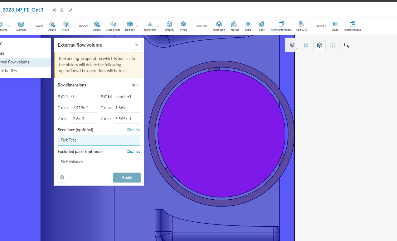
I’ll review this tessellation issue with the team, but I’d suggest trying to create the Flow Region body in your own CAD tool to mitigate this due to your time crunch. You can just create a rectangular box around your body as you’re doing here, then do a of a Boolean > Subtract operation in your native CAD tool. Then, I’d just import that Flow Region body (without the solid body of the car).
To answer your performance question, normally the answer is the car with the lowest drag!
It isn’t a simple question to answer without some detailed review, or a CFD analysis as you’re doing now. Besides, the point of the competition is to figure that out yourself
I’m afraid our engineer is already asleep Would it also be fine to just simulate the front spoiler, since its the only thing that changes throughout all of the simulations?
That might end up being easier and circumventing the problem