Hey @jousefm
Project Link
I have been trying for a couple hours now to get this mesh to work, any ideas? Ive checked the other threads with this error code and there wasnt much to see. What is the main reason for this message? Any way to make this a less general error code. Thought you might want to forward this problem.
Dan
EDIT
Original file was a STEP assembly file Uploaded from Catia V5. NO zip file consolidation
Native CATIA file (with Zipped assembly file) did not upload at all
IGES is currently working without problem
Hi Dan!
Thanks a lot, will forward this issue to my colleagues from the Mesh/CAD team 
Best,
Jousef
No problem.
Is working at Simscale a 24/7 job haha
Is that a question or a statement? 
2 Likes
Hi Dan,
good to see you again Hope you’re doing well.
I took a quick look at the backend which told me that there is a layer refinement on an entity which cannot be used for layer refinement. The only entity type we support for layers are faces which belong to solid bodies. Under normal circumstances the UI shouldn’t allow the user to get this wrong in any way so there certainly is a bug somewhere - either in the frontend, in the CAD or in the meshing stack.
Might I ask you to keep the original setup intact so we can use it for debugging purposes? If you need to proceed, you can copy the meshing setup and double-check all layer refinements.
The fact that it worked fine with IGES tells me that it’s probably something subtle in the CAD. When the same model is represented differently in two formats, it typically points to very small aberrations, such as high model tolerances (which are absorbed in one format, but not the other). It is possible that the “same” model actually represents two different things but those differences might not be visible to the naked eye. CAD is a messy business sometimes and we do our best to minimize such differences but we are not able to prevent them fully.
Jousef is going to track this issue in our database so we can take a deeper look.
By the way - a little side comment: whenever the UI shows “an error occurred”, it’s always a bug. This is our last resort error message which we show in case we’re unable to give a better error message with an actionable fix. So, as a general rule, you can always report such errors, and we need to investigate them.
Johannes
1 Like
Everyone wants to be involved with this issue 
Did you try the standard mesher? It worked fine for me on the last step you uploaded (just the fluid region for now)
@jprobst thanks for letting me know!
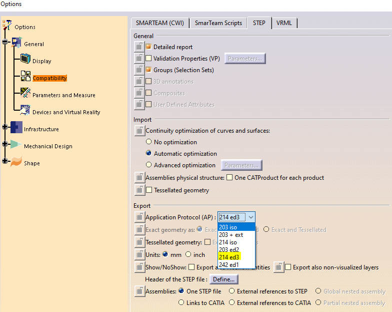
I was wondering if it was a problem with my upload or not. I changed the Export option from the STEP and now it works. Before it was 203 iso and now i changed it to 214 ed3. Not sure if that has an effect. I switched back to STEP from iges because an IGES upload had merged some of the geometry faces.
I can definitly leave the mesh run in the project. I have simply moved on with other models.
For the error message maybe just change it to “an unknown error occured contacting support is required” … something like that so the user knows to report this and doesnt think they have to change something to make it work again.
Dan
@Jon_Wilde
I have never used the Standard mesher. I go straight to Hex Dominant Parametric for more control haha
But why?
Is the additional control helping improve accuracy or is it more what you are used to?
If the former, what additional controls do you need?
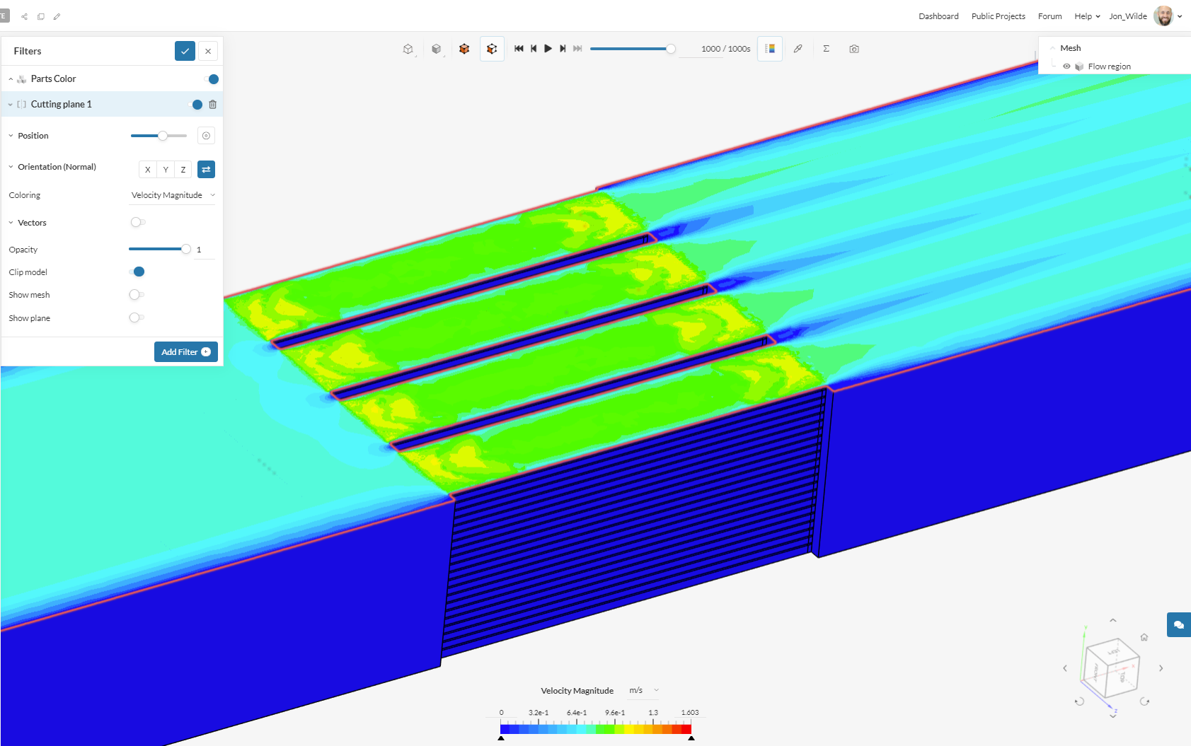
I meshed and ran this in 2 hrs btw, all standard settings (and just the fluid).
Might make sense to add more fluid gap elements but other than that, it should be really great IMO
The additional contol is definetly needed, and its what i learned on.
I am currently testing only a small section of the radaitor in order to get the mesh settings correct for full Rad implementation. This section is about 50mm X 50mm. I need to simulate a radiator that is 332mm X 295.5mm (this is already halved)
Therefore its critical that i am able to get a good mesh with a very very low cell count on this trial run.
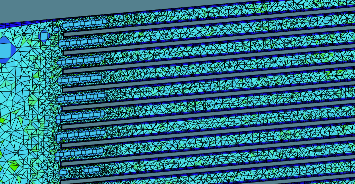
My main probem is that the 1mm gap between fins doesnt allow me to use a 1mm cell size (about LVL 4) the only mesh i got through is with LVL 6 = 0.02mm (fin edge size) but then the mesh is at 8 million cells, so waaay to high. I have to somehow mess with the surface /region/feature refinements to get what i need.
I have already split the fin/lamellen faces to have a higher cell count there, then the main core can be meshed with coarser cells. Not the easiest task
Dan
Wow, that’ll be a large sim! Do you need to run with both fluids, hence the full region?
no just air… i need the pressure drop VS velocity data to use for the porous media coefficients.
Ah OK, so you need a low mesh count to be able to run lots of studies to characterise the porous media?
Is your main limitation here core hours or time?
And then you will run the full model without all the detail (using a porous media instead)?
My main limitation is the 20 million cell limit when using 32 cores. In order to have a decent mesh for when im ready to simulate the half radiator these tests have to have a low total cell count. I have to do 4 radiators in total to get porous media data for each.
This one has the largest radiator dimensions so im starting with that to get the methodology down.
Yes exactly
Ah OK, thanks for sharing.
I have what I think would be a great mesh with the 1-click approach (2 gap elements) but it’s 36m. I would suggest slicing it in 1/2 (or more) again and running that for the characterisation.
I’ll try with 1 gap element incase but also ask if you can still reduce the section down.
I used to do this a lot in the past, and take as few paths as possible to characterise.
Here’s the current:
1 Like
Yea i read something once about gap elements… here it is briefly described. Is there a way to use this in Hex dominant parametric or is this only for the standard mesher?
Being able to define a fixed gap size between fins would be great
Ah but you are using tetrahedral meshing
AFAIK, it’s only for Standard. It’s a super useful feature, I agree.
I’m using hex-core, would be fine
ill give it a shot… hopefully it wont use too many cells 
Cool, check mine if it helps.
I thought I would at least run a comparison, see if I get the same results with the standard mesher 
thats really interesting. I havent used this mesher yet. Thanks for the link!