Your 2 gap elements mesh looks good! but its at 17 Mil cells haha.
Quick question on this. My goal is to get pressure drop VS velocity data. If i Simulate 1/2 the radiator I can just double the results correct?
It seems like a dumb question but i could see the smaller domain somehow effecting the pressure results where simply doubling the result wont be correct. I done have much experience in this field but if this does work then couldnt i just cut my 1/2 radiator sim in half again.
With a 1/4 sim i wouldnt have to worry about my 20 million cell limit
It would remain the same dP as the area changes. So once you catagorise it for a 1/4 model (or even less), you’re set for the full scale.
This is provided you keep the same inlet velocity, that part is important
yea the inlet velocities would be the same then. Im going to simulate at 4-5 different speeds to get a pressure drop VS velocity curve for the Darcy-Forchheimer Coefficients.
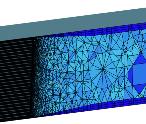
Ah ok … For my run i tired a gap factor of 1 to try and force only a single cell between the gaps. The mesh looks good but its at almost 10 million cells. However its crazy that it only takes 3 core hours. Is the tet mesher that much more efficient or is it due to the standard mesher?
So the standard mesher can create hex-dominant meshes, too (it actually does that by default). The surface mesh will always be triangular – which suggests that it’s a tet mesh but in fact isn’t.
The boundary layers will be extrusions of the triangles into prisms (or “wedges”). Then there will be a buffer layer with pyramids (= 1 quadrangle & 4 triangles) and then finally hexes on the interior.
It comes as a surprise to many of our users because the meshes look like tet meshes and some users have an aversion against them. But most of the cells are actually hexes. It’s just the areas near the boundary which have pyramids and prisms.
I’d recommend you give it a shot! The mesher is now our main mesher and has been well adopted by users and customers for all kinds of things.
Id really like to get into it when it is acceptable for External CFD use. I know TET meshes are more for FEM and HEX is better suited for CFD. However the Extremely low core hour usage is a huge advantage.
Ill defintely be looking into this more as the one mesh i did do was very nice.
No more headaches trying to get the mesh to cooperate! haha
Yeah the tet vs. hex distinction with FEA and FVM is quite common but tet meshes in FVM also have their place, for example when the the walls are curved in all directions or if there’s no preferred direction in the flow. And like I said above, the meshes done by the Standard mesher are hex-dominant, too, so they will perform well in any case.
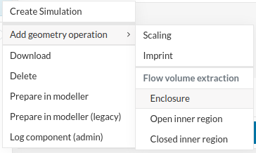
Just to clarify – it is possible to do external aero with the standard mesher, too. You need to do a flow volume extraction of type “Enclosure” first. It will put a virtual wind tunnel around the model. Afterwards you can do external aero with the standard mesher just fine.
it would be cool to see the differnce between the standard VS HEX dominant paramteric. Not only in results but meshing time and core hour use. Ill try one out soon. Looks interesting!
We’ve done a lot of testing, results should be good with both lower mesh times and lower run times
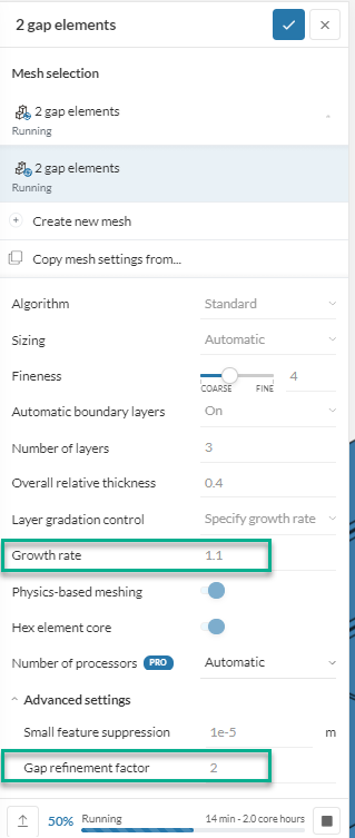
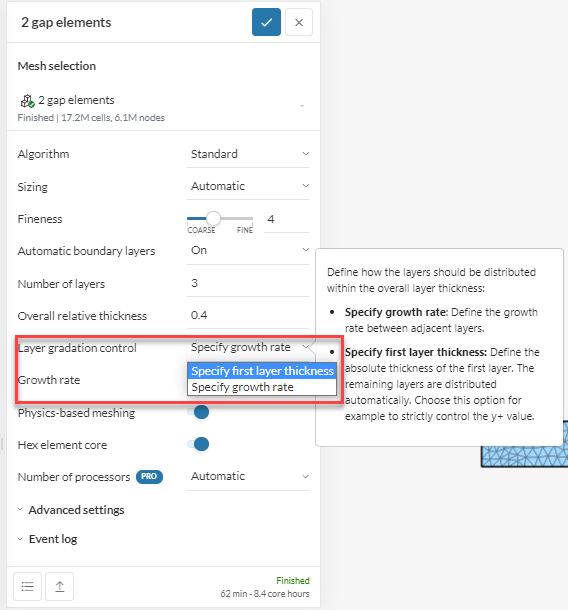
Also, here’s a 1.1 growth rate, a little better I think.
Ah ok. i saw the specify first layer thickness and thought it might be that. Originally i thought it could still be relative layering just with the ability to have a constant first layer only.
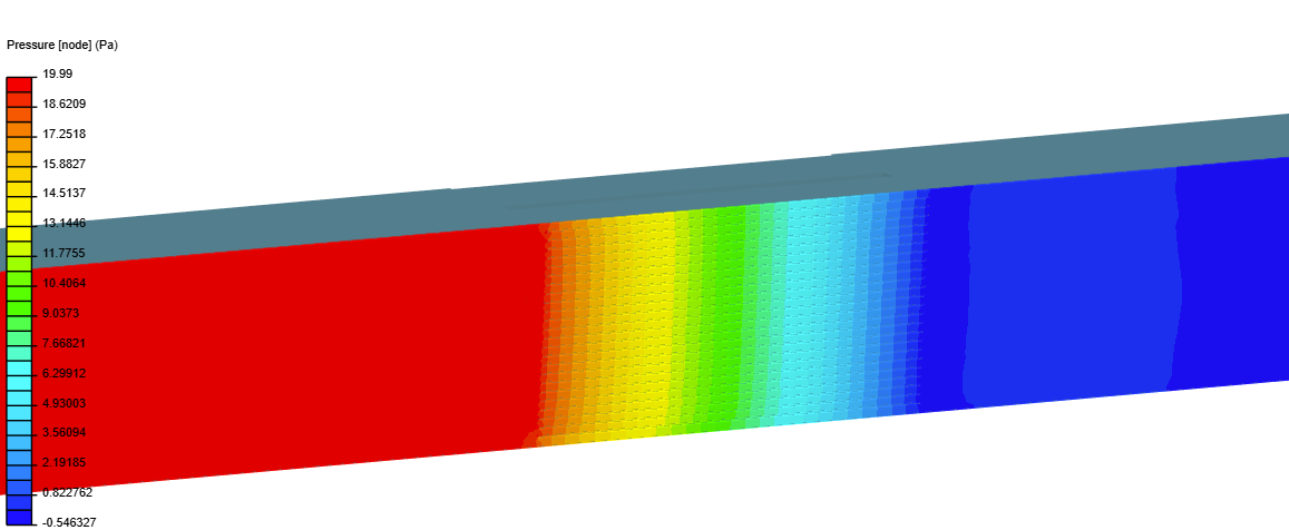
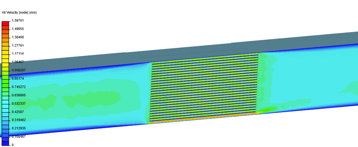
Those results look great!
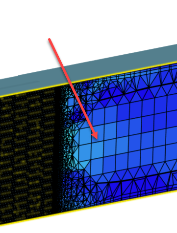
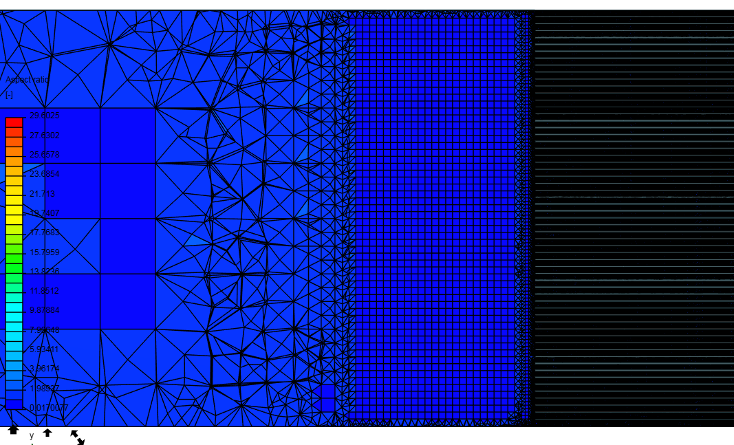
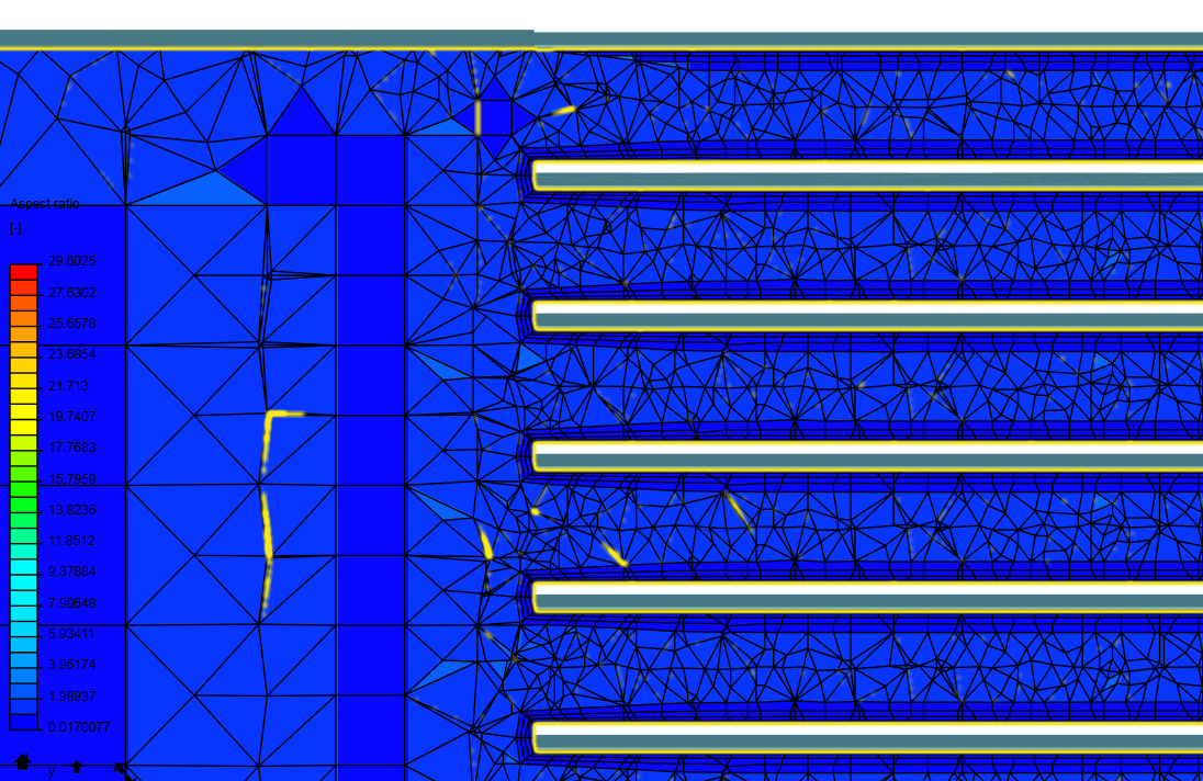
Also not sure about the gap, could just be how the mesh landed on the geometry. I had some of the earlier geometries with a boarder… this one could be one without it where it is cut off at a section with open fins
One other main question is if this meshing system will work with @DaleKramer’s Y+ Histogram Program. Ill have to check that out.
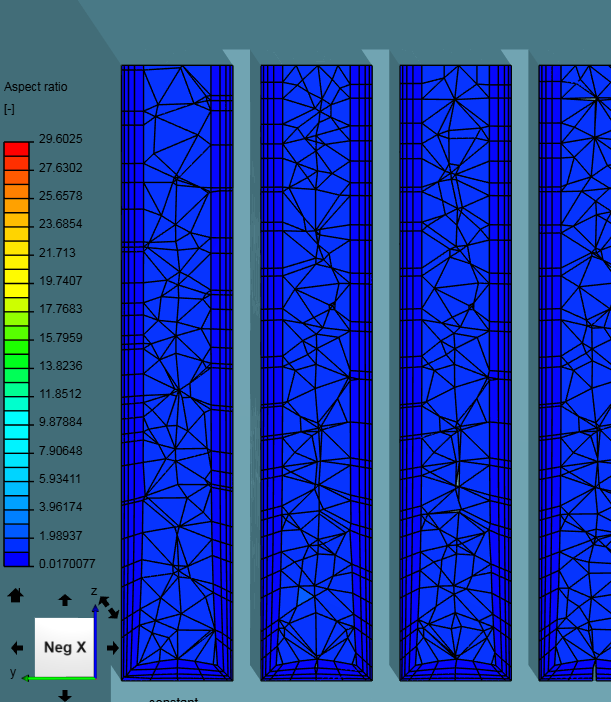
Some quick results — i think im going to be a fan of this mesher.
geometry conformation is great!
I can achieve much higher total cell count the with HEX dominant Parametric - currently at 36 million cells using only 80 core hours and took 150 min.
This was way to high for what i need but useful for a mesh independence study