Drag Coefficient too high

Hi.

I’m doing an analysis of our Formula Student car and it results in me getting drag coefficients that are too high. I have double-checked my input parameters and have followed the webinars. Can you please tell me what I’m doing wrong?

project link:

Best,
Tina

1 Like

Hey Tina,

Your setup looks OK. I noticed that the relaxation factors, under numerics, are slightly different. You used 0.3; 0.7; 0.7; 0.01 for pressure, velocity, k and omega respectively. The step by step tutorial suggests 0.2; 0.5; 0.5; 0.5.
What Cd values were you hoping to get? I tried to find other public FSAE projects but most of them don’t have drag coefficients set in result control :expressionless:
This project by pfernandez resulted in a 1.23 Cd although his geometry is a little bit different from yours. Power User @fsite has a lot of experience with FSAE, maybe she will have further insights.

1 Like

Thanks for jumping in here! Also tagging @yosukegb4 here :slight_smile:

I will have a look at the project in the evening.

All the best!

Jousef

1 Like

Hello @tinaalim it is really nice to see another FSAE project! I am also having a look at your project, and I’ll be right back! :grin:

So I took a look at your project.:grin:

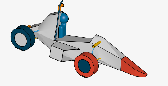
It is a Chassis + Suspension + Wheels + Driver + Sidepod + Radiator model as seen below
Screenshot%20from%202019-11-12%2021-15-52

It is expected that the L/D value will be low enough, and so it is, calculating the total downforce as Fz= -19.657429023096 and the drag as Fx=-185.644100869082 for the whole car.

To begin with the forces:

The wheels produce a lot of drag, which is not really weird, because there is no Front Wing to defect the air around the wheels, as it happens with most FSAE cars , but I had a look at the rotating walls settings, and I would like you to tell me how you set the rotating velocity, because it does not seem right to me. You could use this formula : ω = U/r , whereas r is the radius of your wheel. At 20 m/s , and a radius of close to 0.3, as I can assume from your settings, it is pretty unlikely the ω is 81.73 rad/sec. The total of four wheels produce approximately 70 N of drag, so something could be wrongly set.

The high values of the chassis seem expected for this design, they are not assisted with any aerodynamic devices at this stage, as turbulence is not necessarily bad, it can help re-energize the airflow around the bodywork, and reduce separation. It is also a design with pretty steep angles, like the nose.

So, to me, the simulation seems okay as @Ricardopg said, and you should focus on the actual forces, and initially try a new rotating speed. For the next run, I also suggest you include the forces on the radiator and sidepod as well, in order to monitor design changes as well. The sidepod has many edges too. Try some fillers.:grin:

The reference area seems too small, what dimensions did you use? It does not matter that much though, the real deal is the forces.

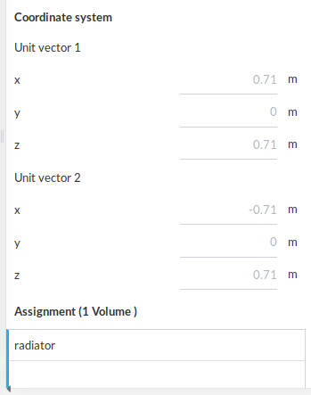
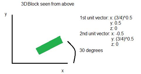
Edit: I also noticed this in the Porous media section:

Screenshot%20from%202019-11-12%2022-44-01

Shouldn’t the x in unit vector 1 be -0.71 in your case?

Best regards,
Fillia

7 Likes

Hi everyone,

I just checked only the result control “whole car offs” of tinaalim’s full car CFD.

  • whole car coffs
    • Drag direction [ -1, 0, 0 ] is correct, not [ 1, 0, 0 ]
    • Reference length should be the whee base length of the car.
    • Center of rotation is at the center of the wheelbase
    • Please check the Reference area value is half of the frontal projection area of the whole car

Please check all the conditions and controls again.

Best,
Yosuke

5 Likes

Thanks @Ricardopg! I’ll try and change it for my next run!

Thanks so much @fsite! Though I followed how to setup the porous zone using Ricardo’s advice which was:

porous

And according to this, I should get a positive x value for my unit 1. Is this not right?

With regards to the angular velocity, my wheel radius is 0.2447 which along with speed of 20 m/s gives me an angular velocity of 81.73 rad/s.

Hi @yosukegb4, thanks for checking my setup. I thought the centre of rotation should be left empty according to the tutorials. If not, would the centre of wheelbase be the the halfway point between my two centre of wheel rotations?

No problem, Tina.

As long as the Darcy and Forchheimer coefficients d (x, y, z) and f (x, y, z) are set accordingly to your unit vectors, I don’t think it’s an issue. If you switch the order of the vectors, you also have to switch the coefficients.

Hi @tinaalim

I hopw this post helps you.

Best,
Yosuke