Recording
Homework Submission
Your task is to investigate the stresses and deflections in a wing when apply bending and torsional load due to wind pressure.
The step-by-step tutorial below contains all of the steps for setting up the simulation in SimScale and visualizing the results.
To submit your homework assignment, please generate a public link of your project (Sharing a Project)
Homework Deadline: December 17th, 11:59 pm CET
Click Here to Submit your Homework
Introduction
This exercise involves simulating the aircraft wing with applied bending and torsional load due to wind pressure. The tutorial below explains how to setup the simulation workflow and then visualize the results. The interesting thing would be to see how the deformation and stresses change with respect to different loading condition on the wing.
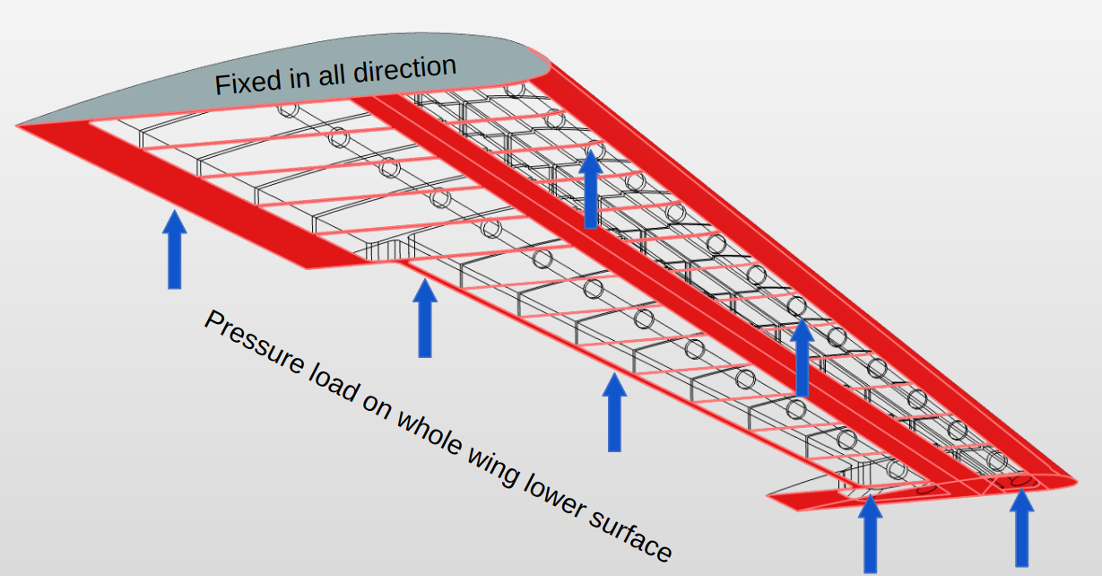
Bending Load
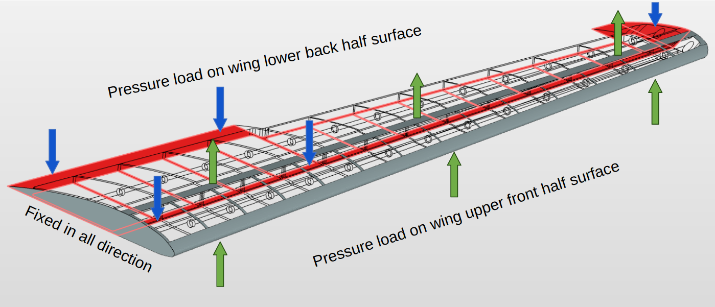
Torsional Load
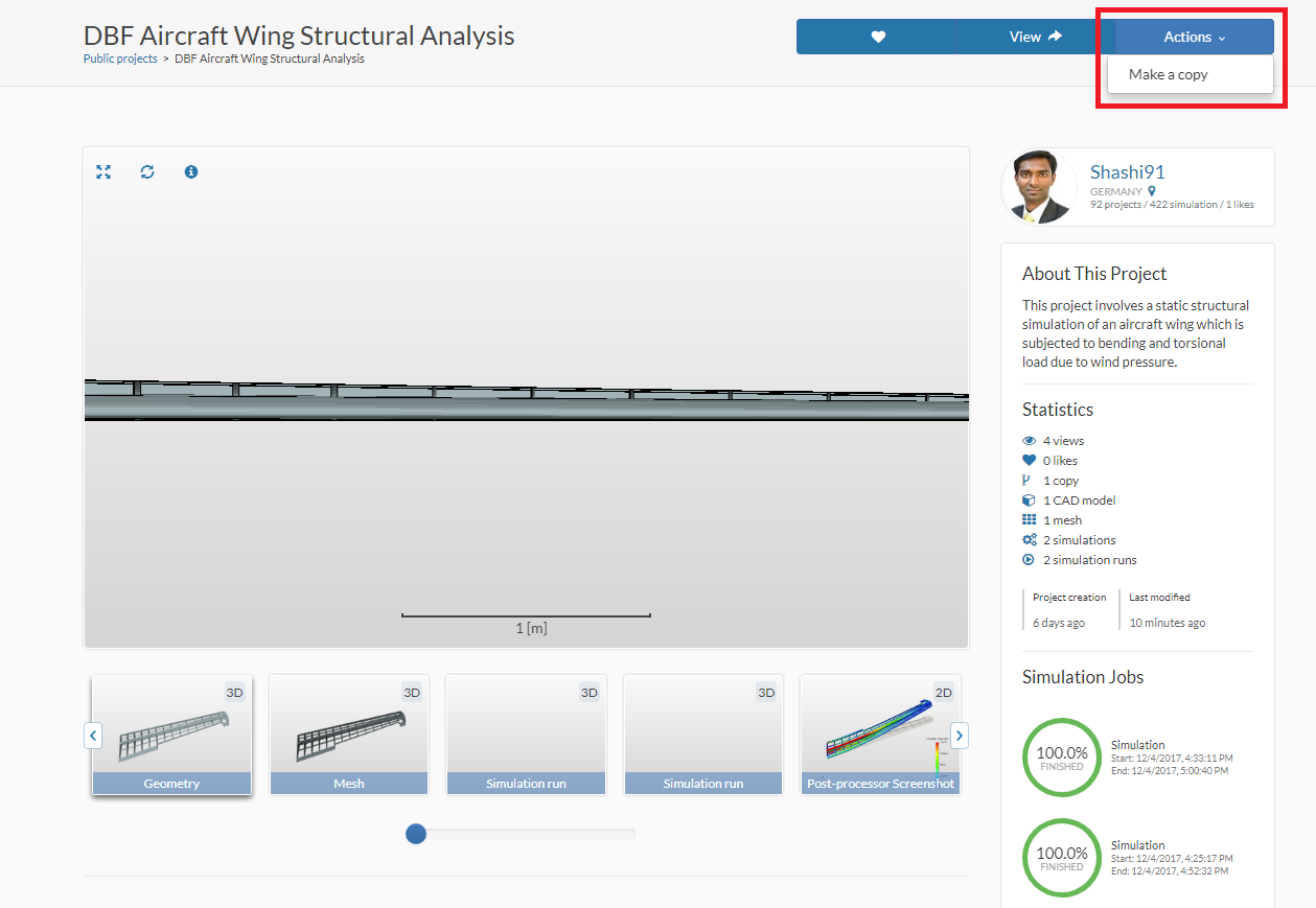
Project Import
To start this exercise, please click on the link below and then make a copy of the project.
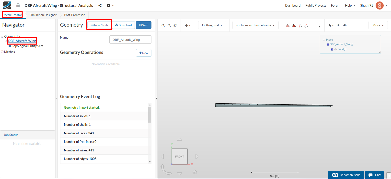
Mesh Generation
In the Mesh Creator tab, click on the geometry DBF_Aircraft_Wing
Then, click on the New Mesh button in the options panel.
Select Tetrahedral dominant mesh and select the following parameters - Second order under the desired mesh order, 3-Moderate for fineness and 8 cores.
This operation will automatically create a mesh for the geometry. The cell size and refinement will be adapted automatically.
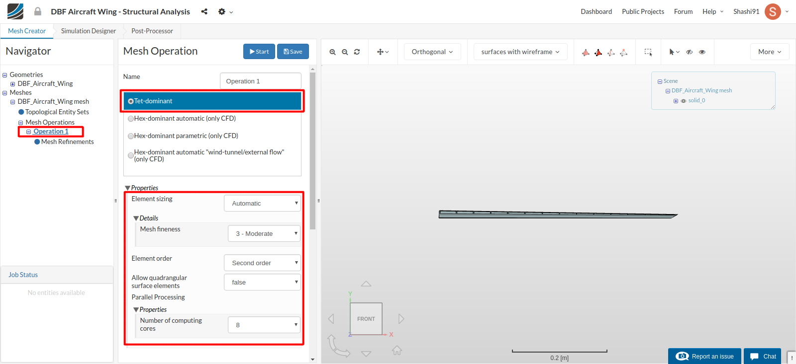
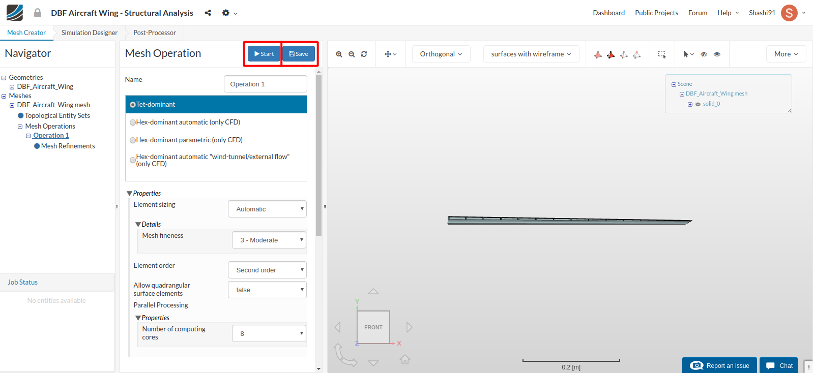
Click on the Save button to save all settings.
Now click the Start button to begin the mesh operation. The meshing job will start in a few moments. All computation is done via cloud computing.
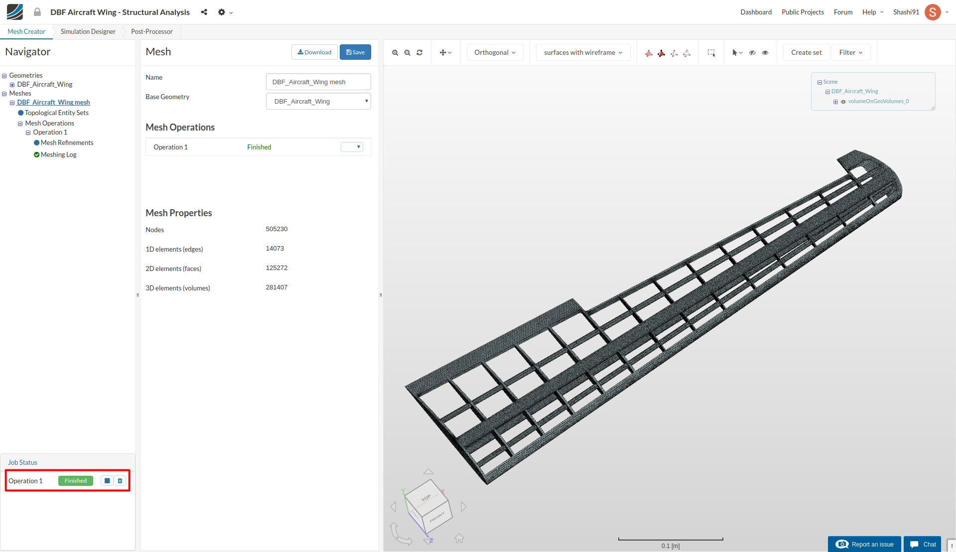
The mesh operation takes about 6 minutes to complete and gives a Finished status in the lower left status panel once it is done.
Simulation Setup
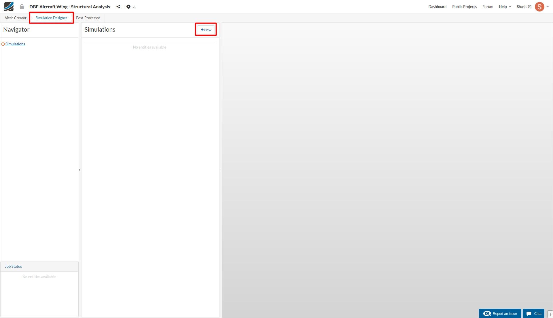
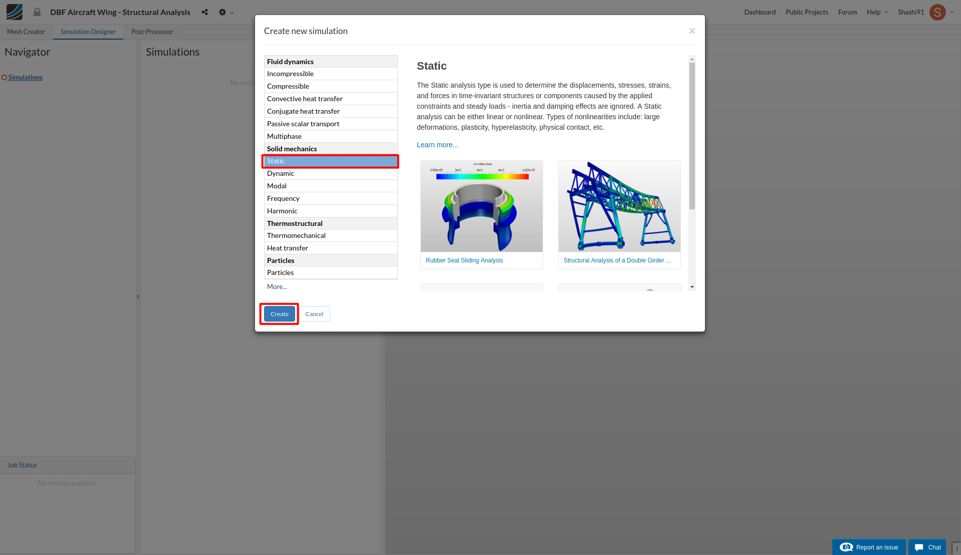
For setting up the simulation switch to the Simulation Designer tab and select New simulation.
A Create new simulation window will pop-up. Since our load will be static and deformation will be large, select the analysis type Static under Solid mechanics and click create.
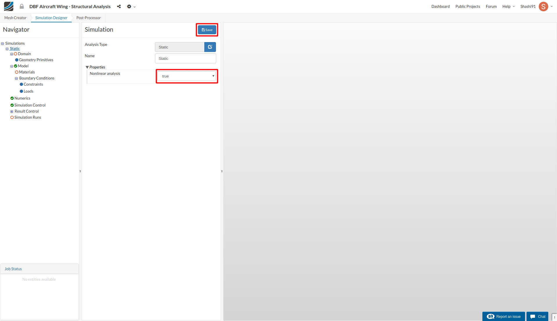
Change the Nonlinear option to true and click Save.
Domain
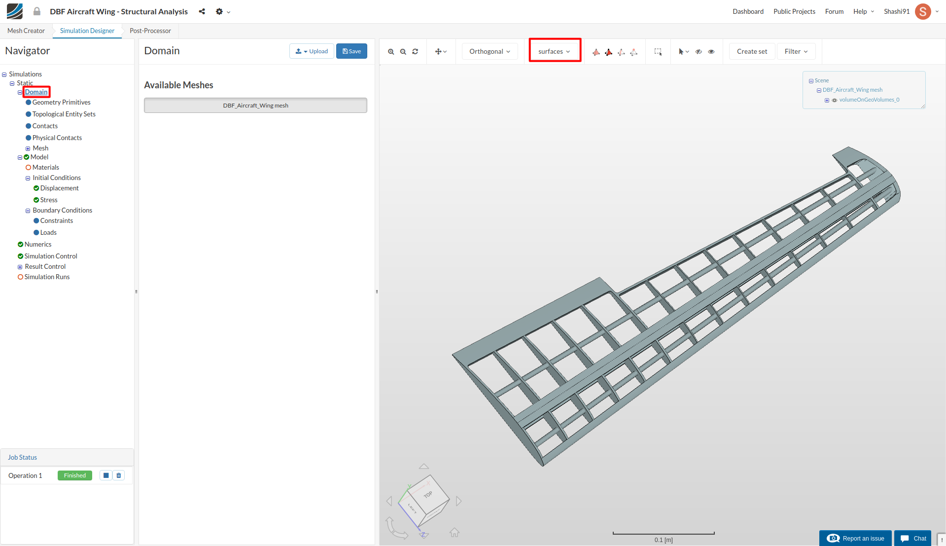
Click Domain from the tree and select the mesh created from the previous task. Click the Save button. The mesh will then automatically load in the viewer.
Furthermore, change render mode to Surfaces on viewer top to interact with the mesh more easily.
Topological Entity Sets
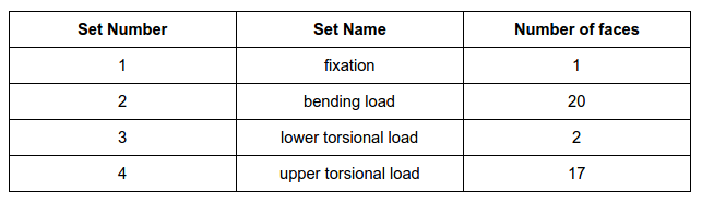
In this tutorial we are going to perform 2 different simulations as discussed earlier. The image below shows settings for bending and torsional load condition. It is convenient to name these under Topological Entity Sets to be used later during the setup.
We will create 4 sets in total, as shown below:
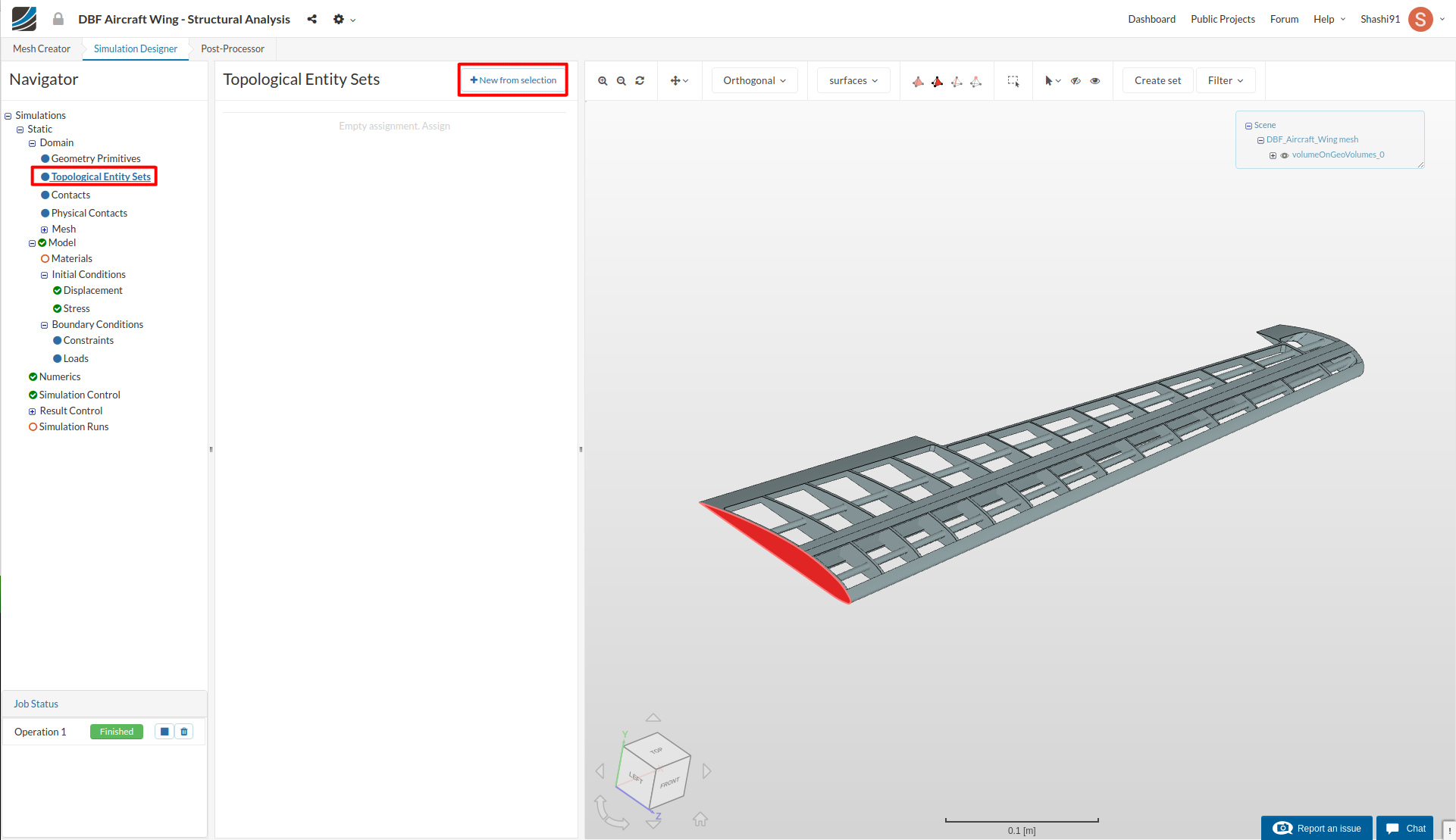
Click on the tree entry Topological Entity Sets.
fixation:
To create the first set, click the shown surface and click on the New from selection button to create a set named fixation.
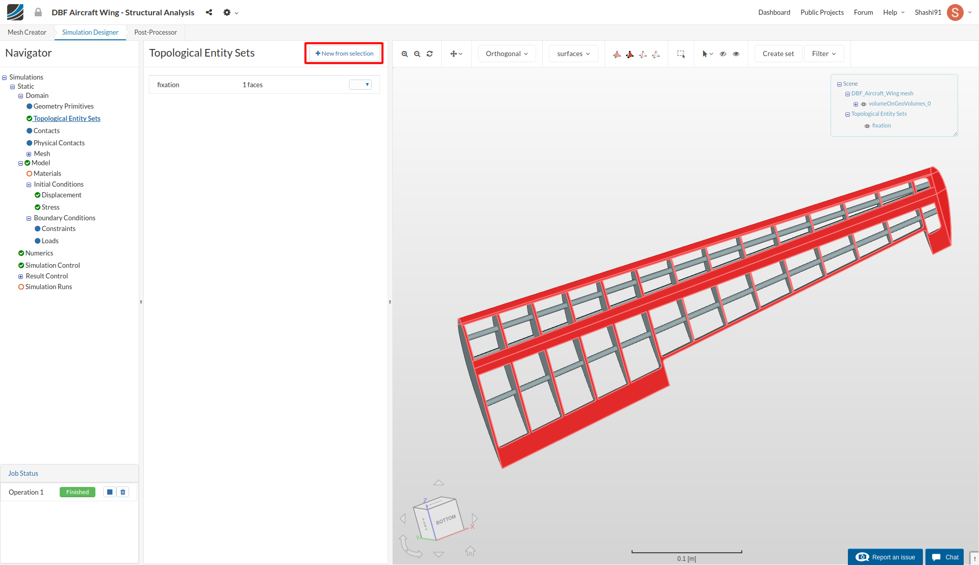
bending load:
To create the second set, flip the model upside down and select the shown faces (all lower faces of wing), follow the same procedure above to create a set named bending load.
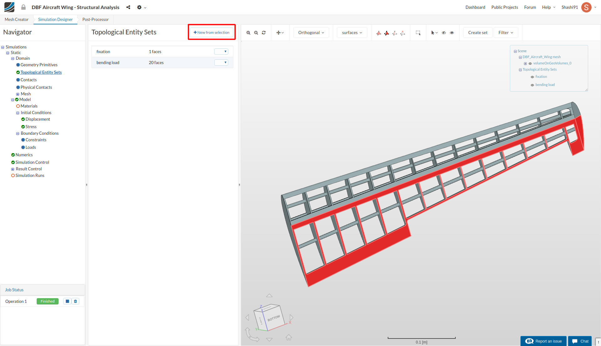
lower torsional load:
To create the third set, select the shown faces (all lower back half faces of wing), follow the same procedure above to create a set named lower torsional load. (ignore the warning that pops up, it just tells you that you have selected the faces which are part of some other topological entity set)
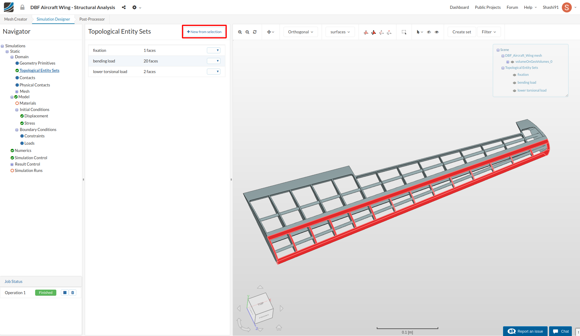
upper torsional load:
To create the fourth and final set, flip again the wing upside down and select the shown faces (all upper front half faces of wing), follow the same procedure above to create a set named upper torsional load.
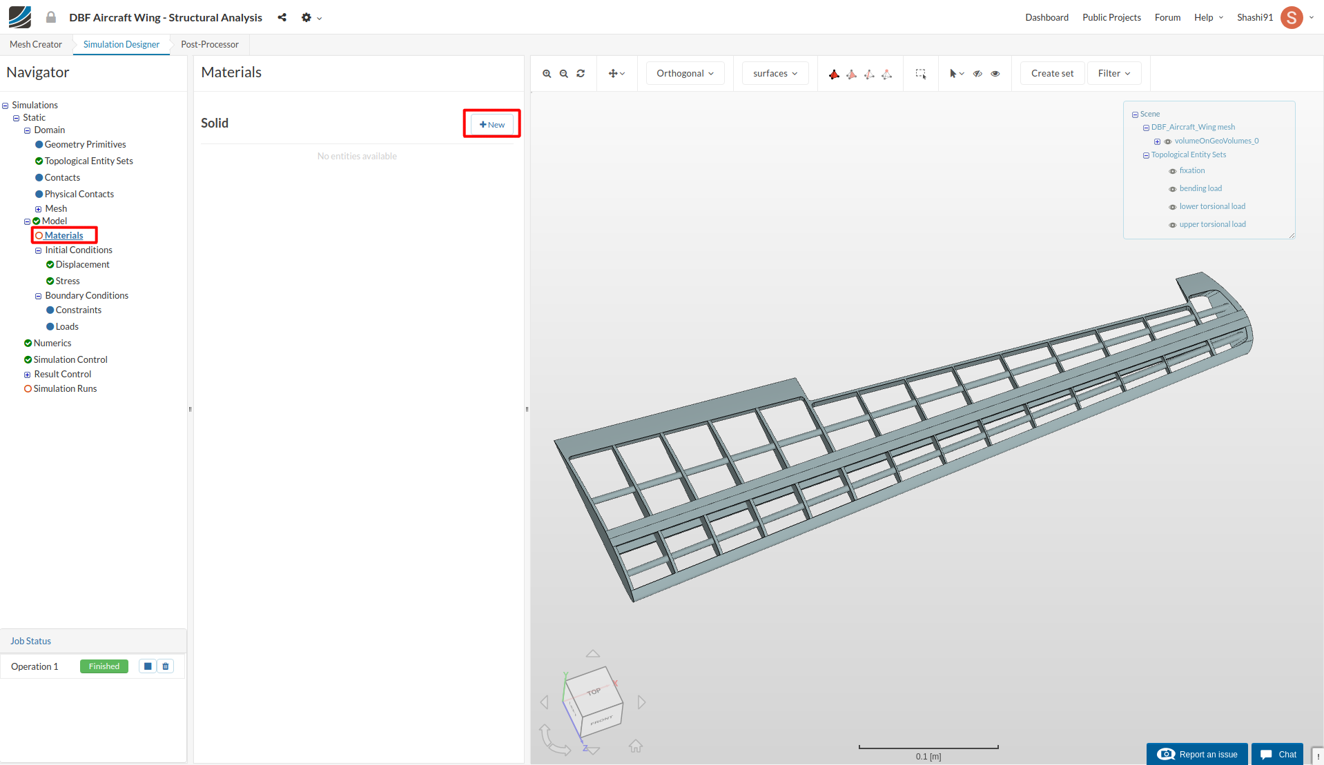
Material
Now we will define a material for our wing. Material properties of Balsa wood with very low density is assigned to the whole geometry. Select Material from the sub-tree and click New.
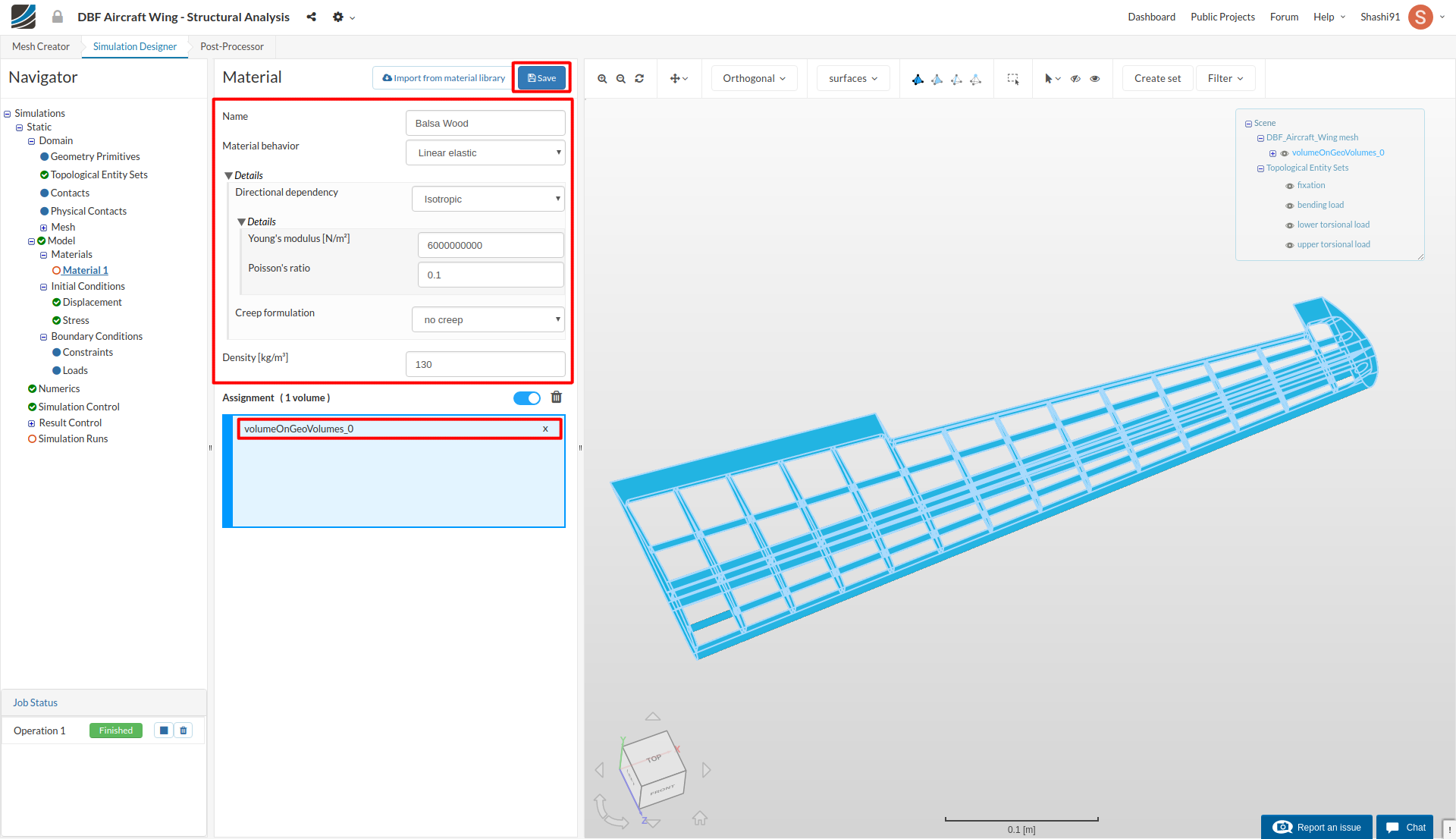
Change the Name to Balsa Wood (optional). Then:
- Young’s Modulus [N/m2] to 6000000000 (defines the stiffness of the material).
- Poisson’s ratio to 0.1 (defines the relationship between deformation of a material along perpendicular axis).
- Density [kg/m3] to 130 (defines the self load of the geometry).
- Select the volume under Topological Mapping and click Save.
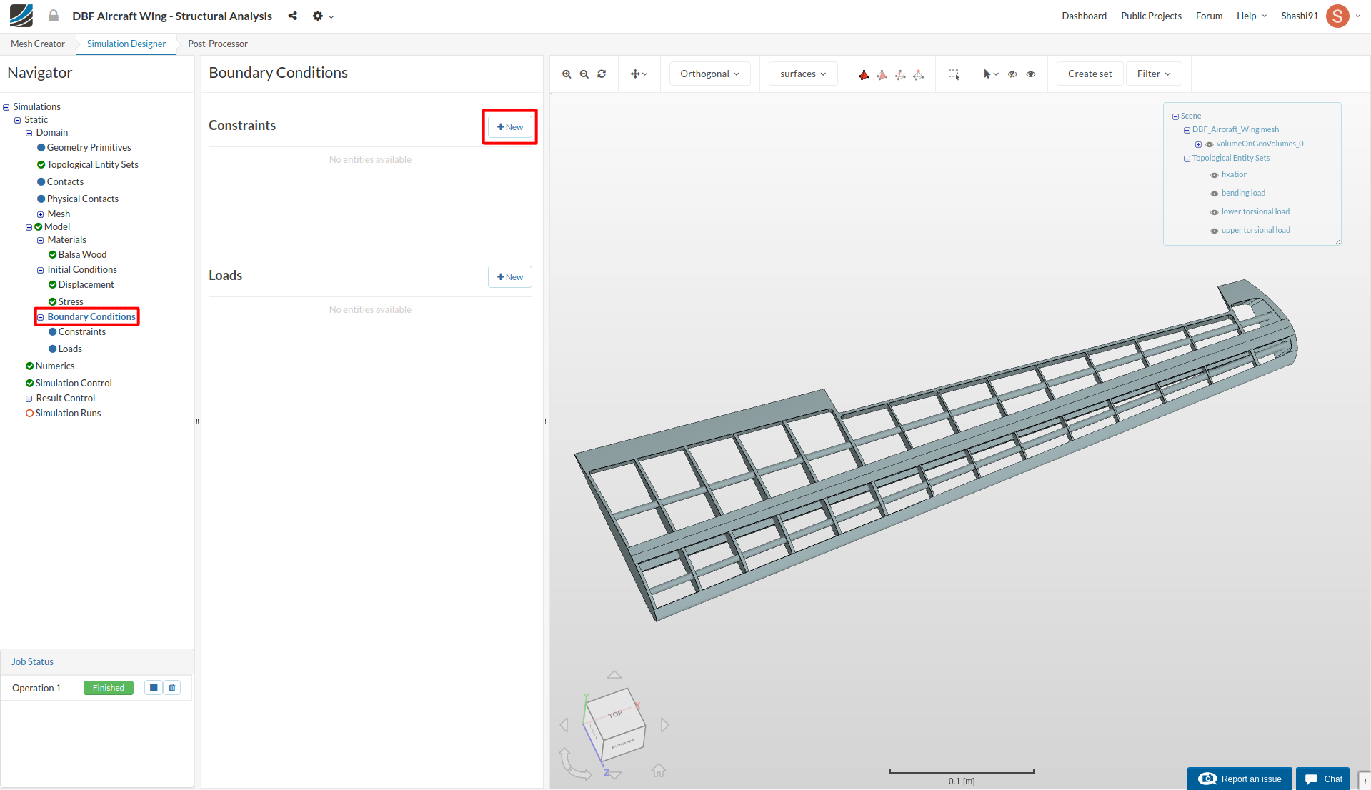
Boundary Conditions
In this section, we will define the constraint (fixation) and load (bending load) for our simulation case.
Let’s first define fixation. Select Constraint in the tree and click New.
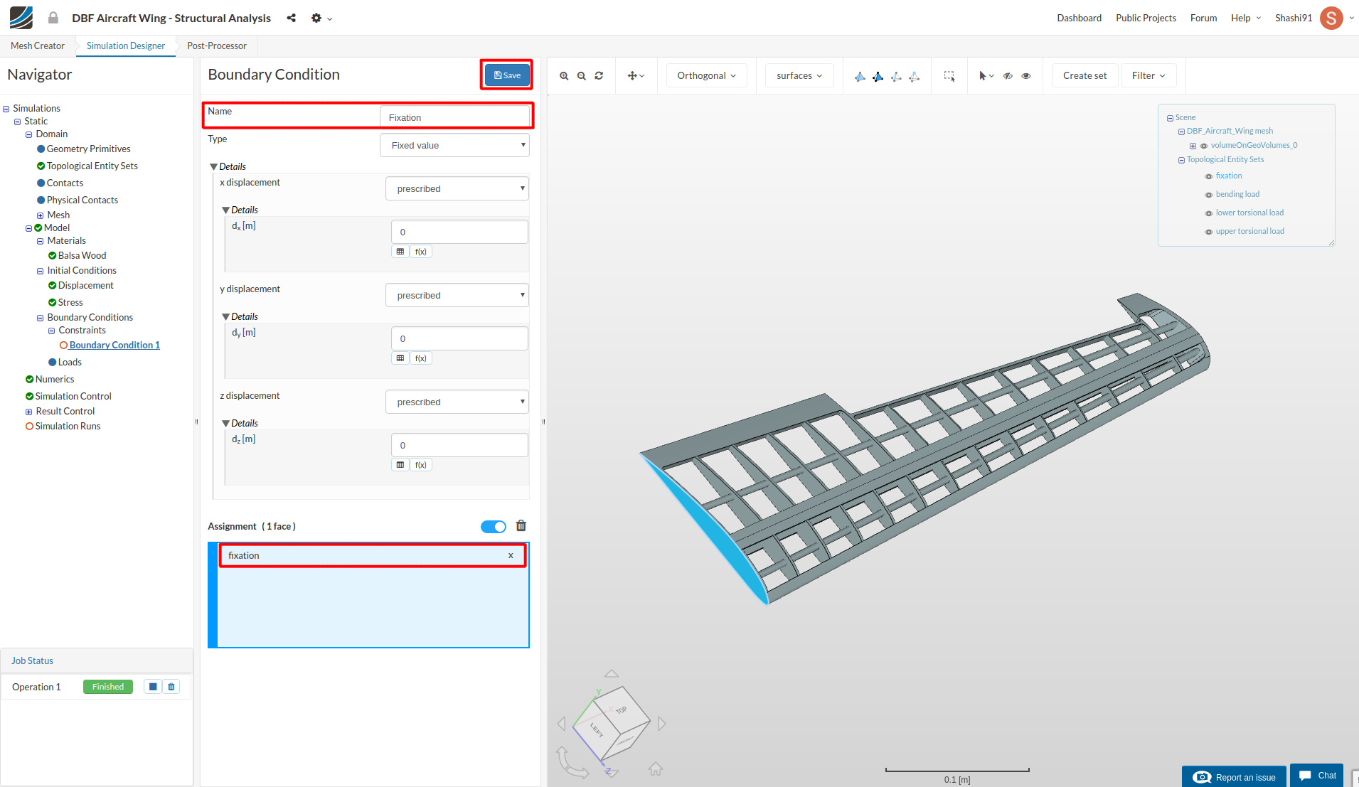
A new boundary condition with default name boundary condition 1 will be created. Rename it to fixation (optional).
Under Topological Mapping, change Filter for entity types to face sets and select ‘fixation’. Then click Save.
Next up, we will define the boundary condition for bending load. Select Load in the tree and click New.
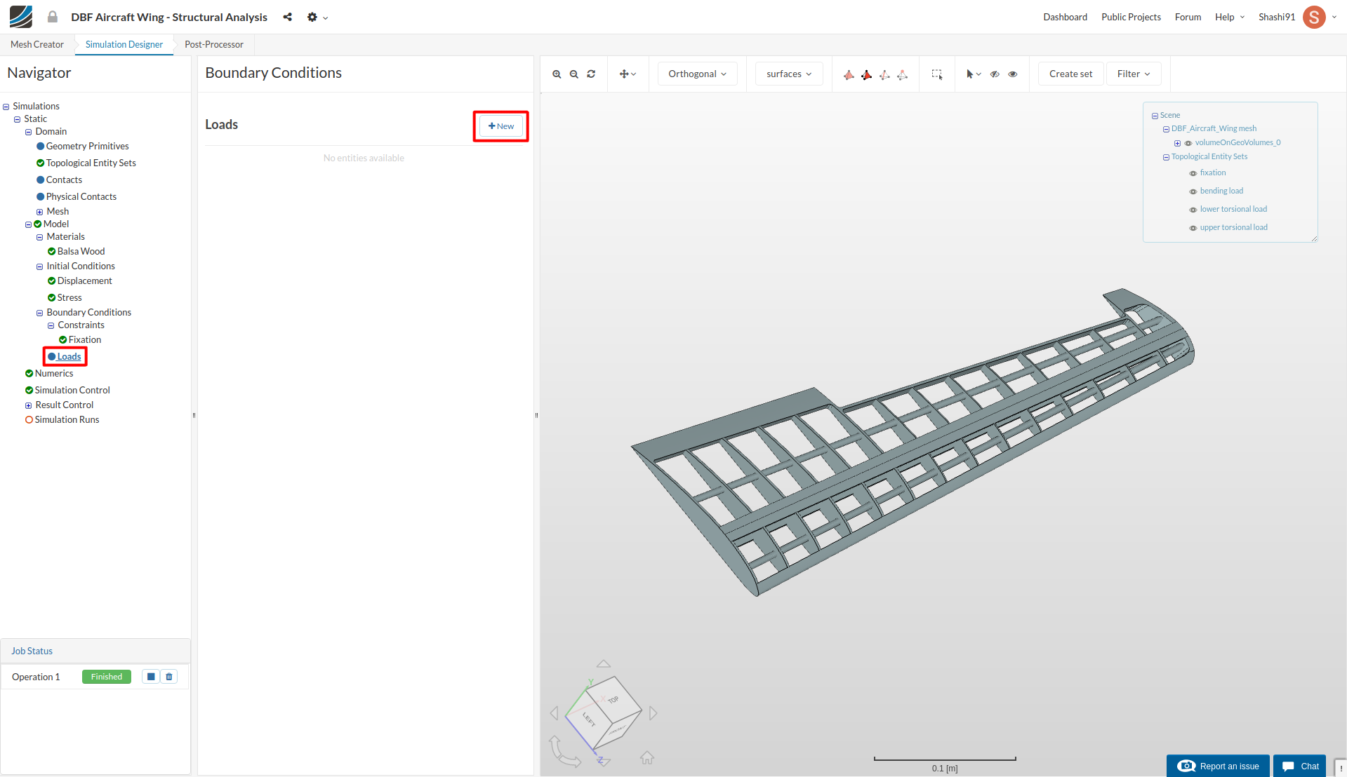
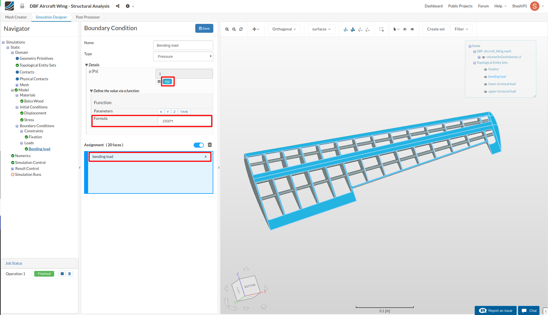
A new boundary condition will be made under Load. Rename it to bending load (optional).
Click small f(x) button under Pressure and give this formula 1500*t. (this formula will apply a pressure load of 1500 Pa on all lower faces of the wing linearly over time. Time is multiplied since the solver can’t automatically ramp the load over time).
Select bending load under Topological Mapping and click Save.
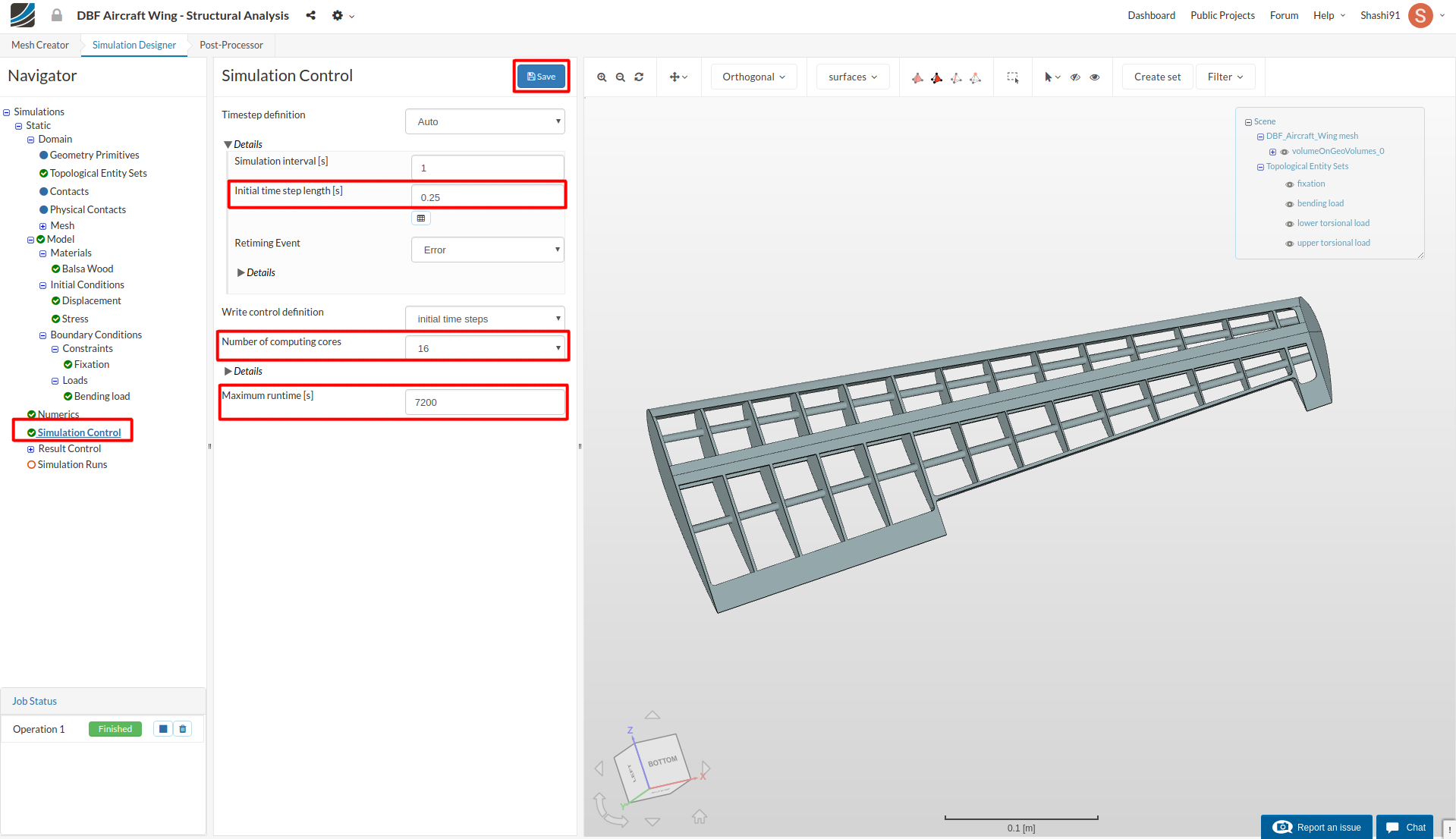
Simulation Control
Click on Simulation control and change change Initial time step length [s] to 0.25 under details of Timestep definition, Number of computing cores to 16 and Maximum runtime [s] to 7200.
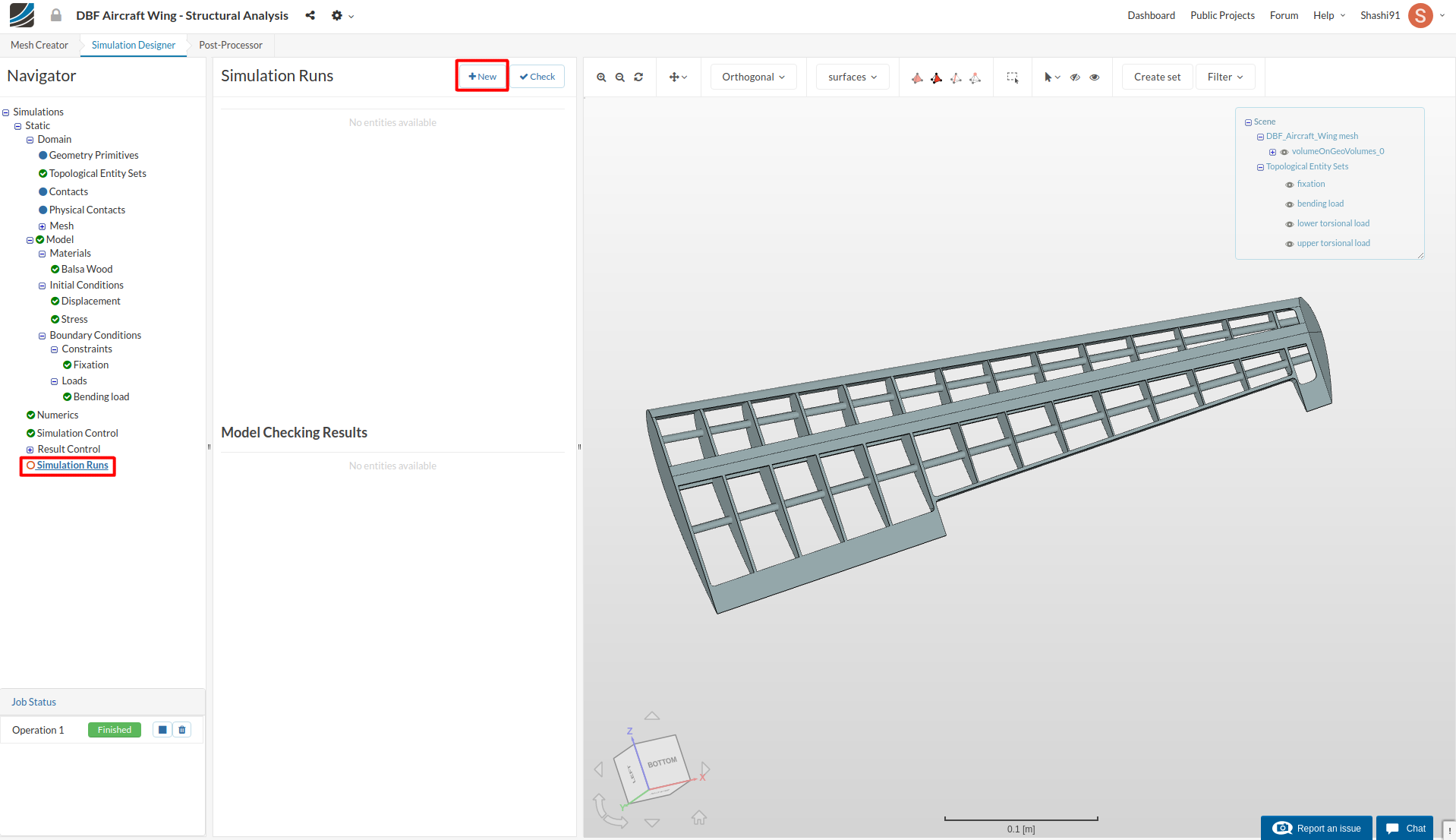
Simulation Runs
Click on Simulation runs and create a new run. Give simulation run a suitable name (optional) e.g. Wing_Bending in this case.
Create Further Configurations
Once you have started the run with the first configuration setup, go ahead and make a duplicate of this simulation in order to perform torsional load analysis (configuration 2).
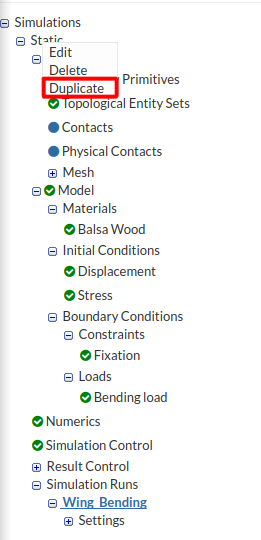
Rename the simulation to Torsional Load.
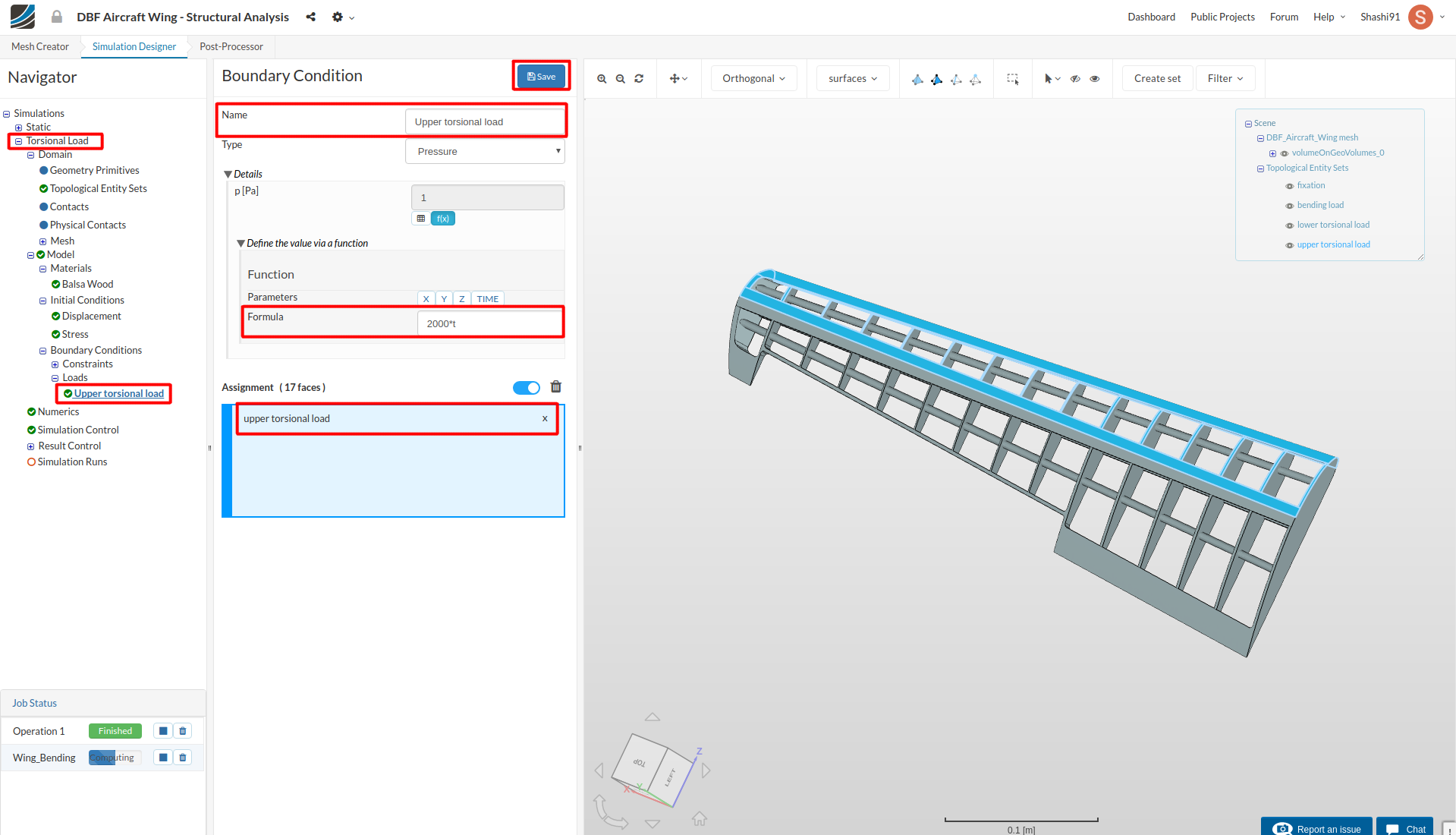
All you need to do is to change the pressure load in this case. Click Bending Load in the tree and rename it to Upper torsional load. Change pressure value from 1500*t to 2000*t, deselect bending load and select upper torsional load under Topological Mapping. Then click Save
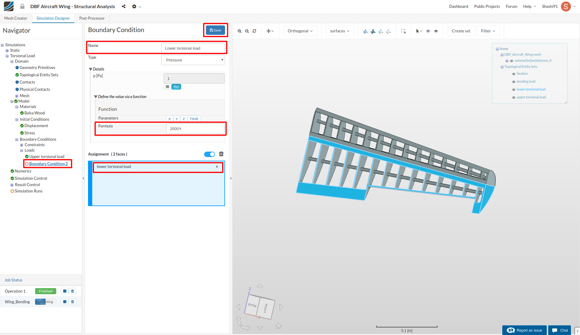
Next create a lower torsional load by creating a new load under Load, rename it to Lower torsional load and give pressure value of 2000*t (similar as upper torsional load). Select lower torsional load under Topological Mapping and then click Save.
Create a new run and click Start.
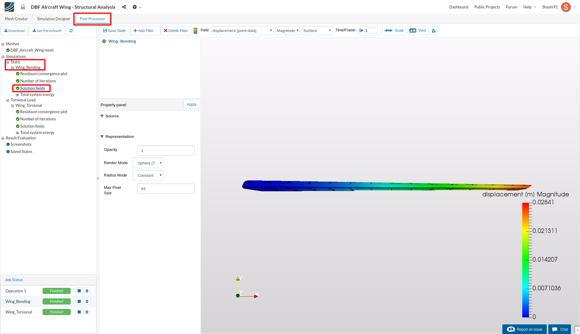
Post-processing
Once the simulation is over, click on Post-processor tab to view the results.
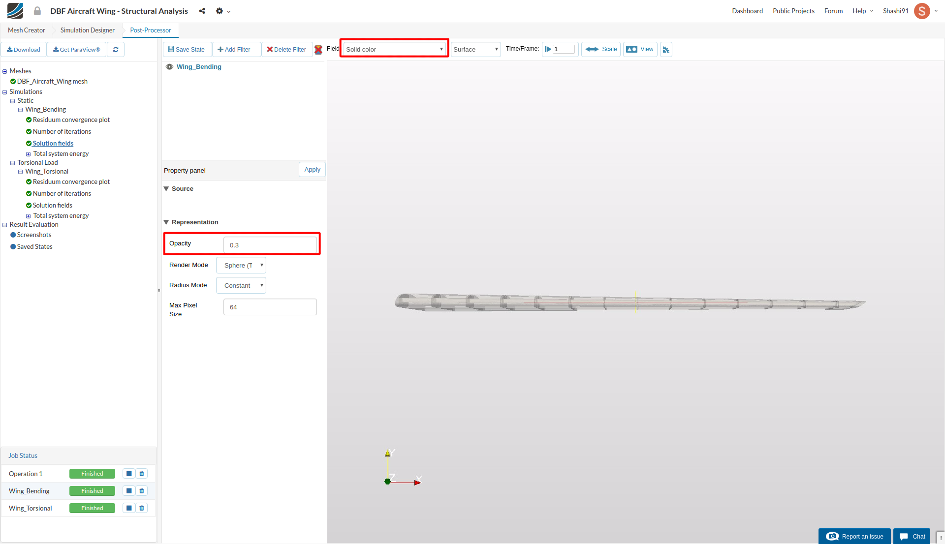
Select Solution fields of the simulation run you want to view results. In this case, it is Static-Wing_Bending.
In order to differentiate between the deformed and undeformed geometry of the wing, make the field (at the top left corner) to Solid color and change the Opacity to 0.3. This will make the wing little transparent.
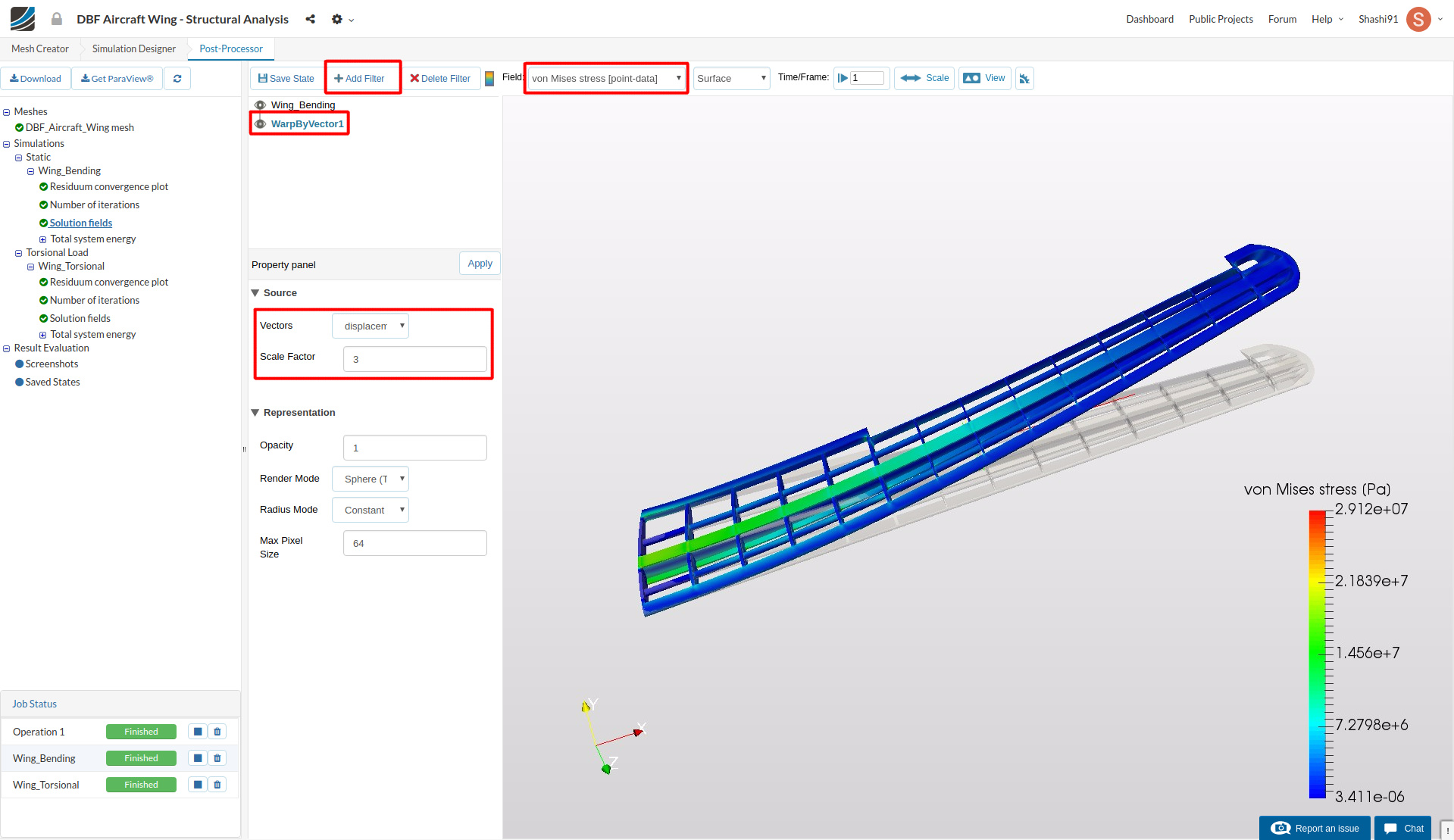
To see the deformed geometry, click on Add Filter and then Warp by Vector. You will see a Warp by Vector filter is added under your solution field and in the result viewer, the deformed wing will appear with the undeformed shape. You can select Toggle color bar to view the magnitude of the von Mises stress (right side of the Delete Filter button).
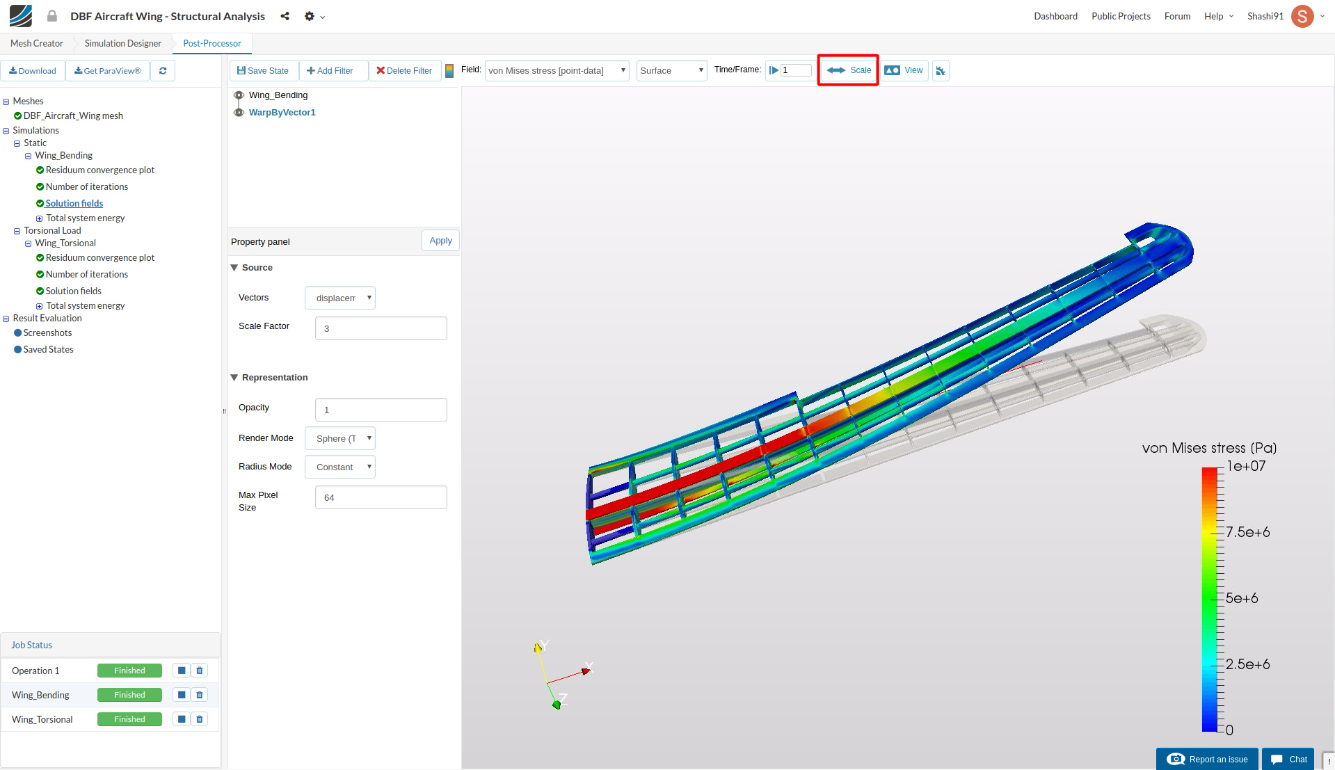
Click on Scale and select the range from 0 to 1e7
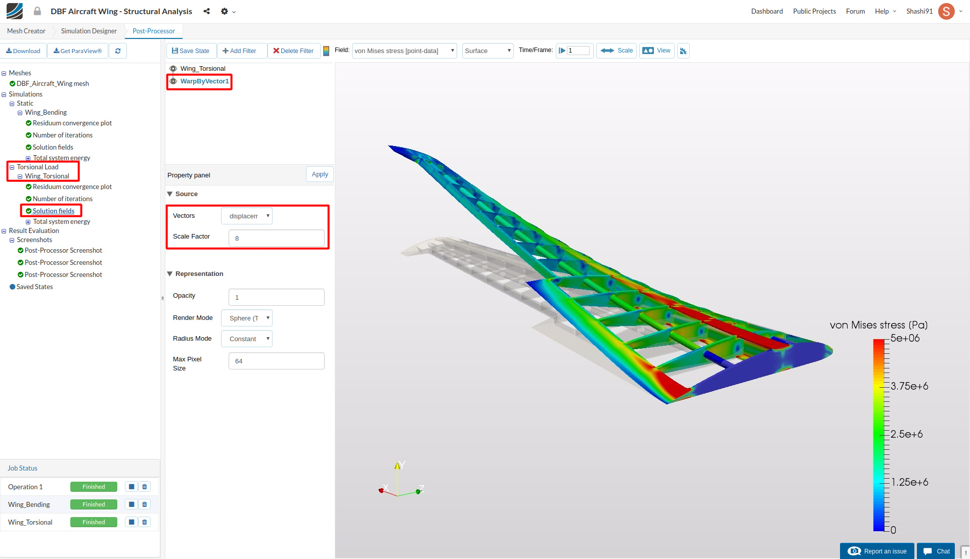
Click camera icon under Viewport Tools to generate a screenshot. The screenshot will appear under Screenshots section of a Result Evaluation tree item.
Similarly, follow the same guide for post processing the results of the torsional loading.
Homework Submission
To submit your homework assignment, please generate a public link of your project (Sharing a Project)
Homework Deadline: December 17th, 11:59 pm CET

