Objective
The purpose of this tutorial is to simulate the heat transfer in a data center. Data centers produce lot of heat which needs to be removed from the room in order to keep the machinery cool. Hence an efficient cooling and ventilation system is essential for these kind of environments. SimScale can be used to simulate the effects of configuration of air inlets and outlets, in order to improve the ventilation. In this tutorial we will setup a simulation for single inlet and single outlet. For other configurations basic simulation steps will be same.
Step-by-Step Instructions
Geometry
CAD geometry can be [imported from here].
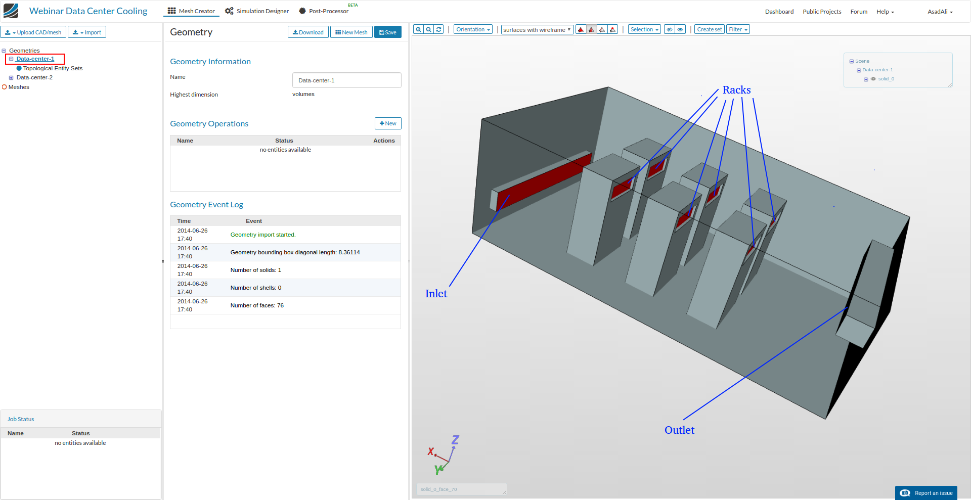
Once imported, project will have two different geometries with changed inlet, outlet configuration. For this tutorial we will use “Data-Center-1” geometry with inlet, outlets as follows:
Meshing
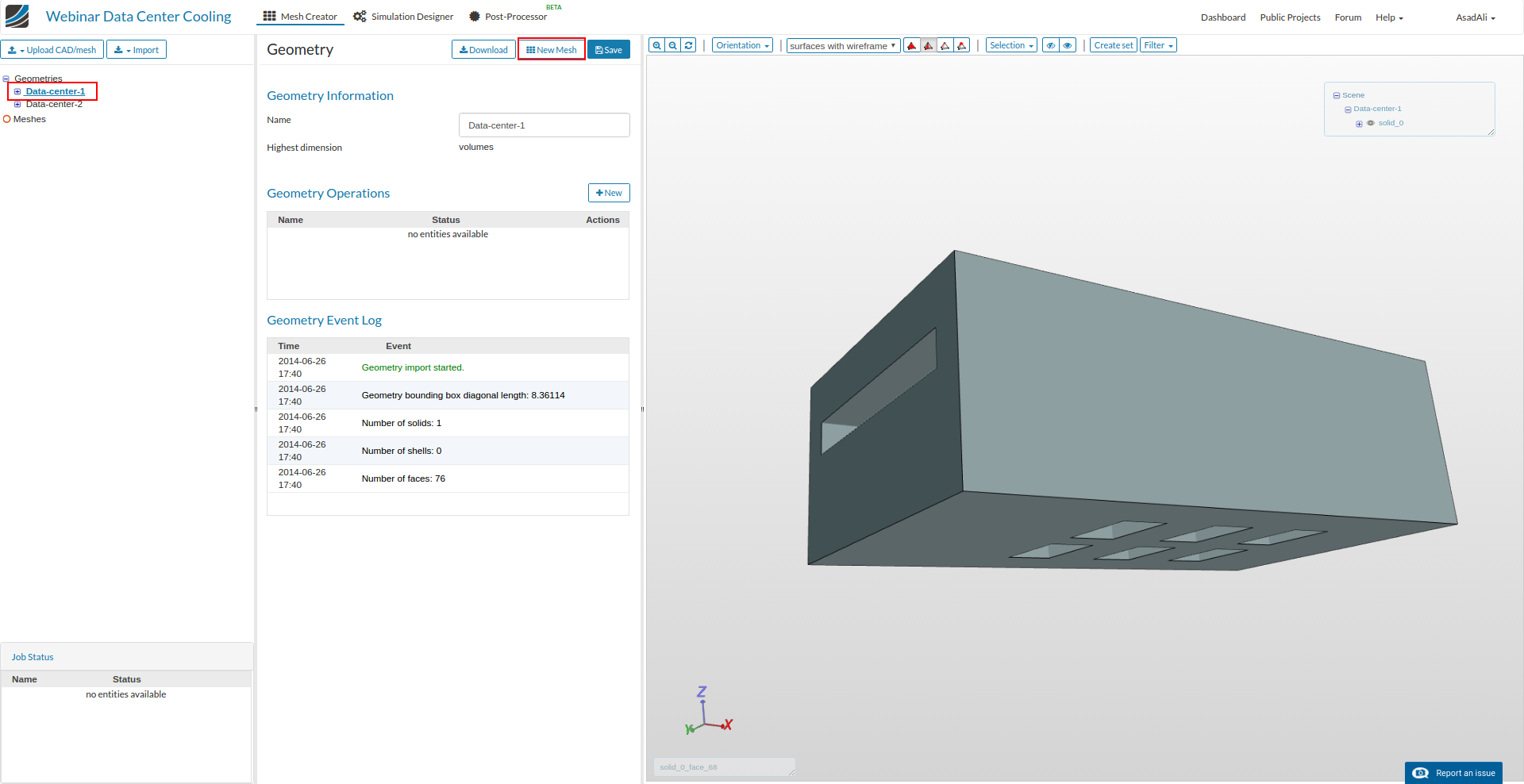
Under the geometry tree, click on the geometry “Data-center-1” . From the geometry options panel, click on New Mesh. This will automatically create a Mesh operation and make the mesh operation selection panel active.
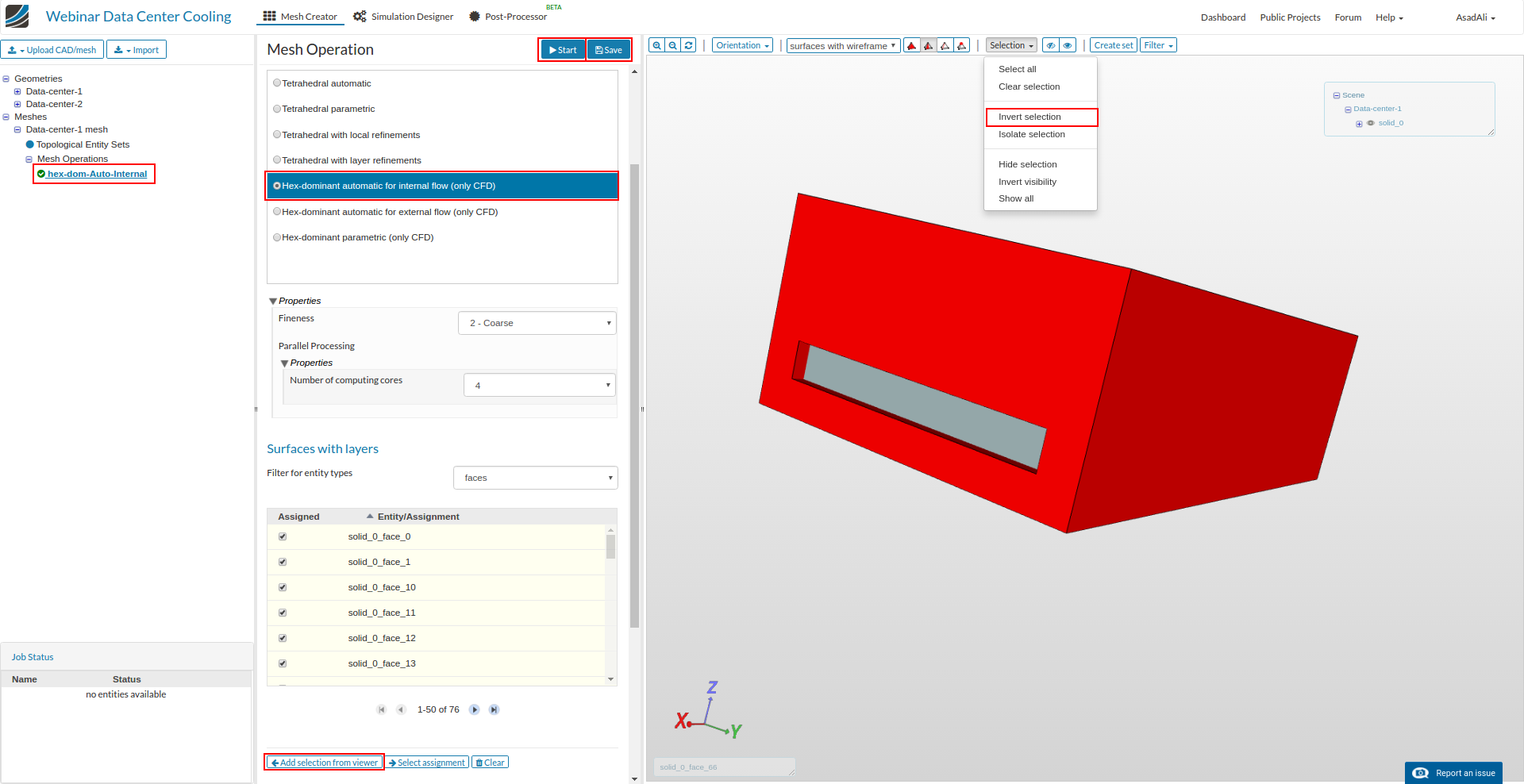
Rename the mesh operation to “hex-dome-Auto-Internal” and select the Hex-dominant automatic for internal flow (only CFD)
To select the faces for boundary layers select inlet and outlet faces, next click on “Selection” and click on “Invert selection”. Select Add from viewer from the bottom of Mesh operation. Save the selection and click “Start” to start meshing.
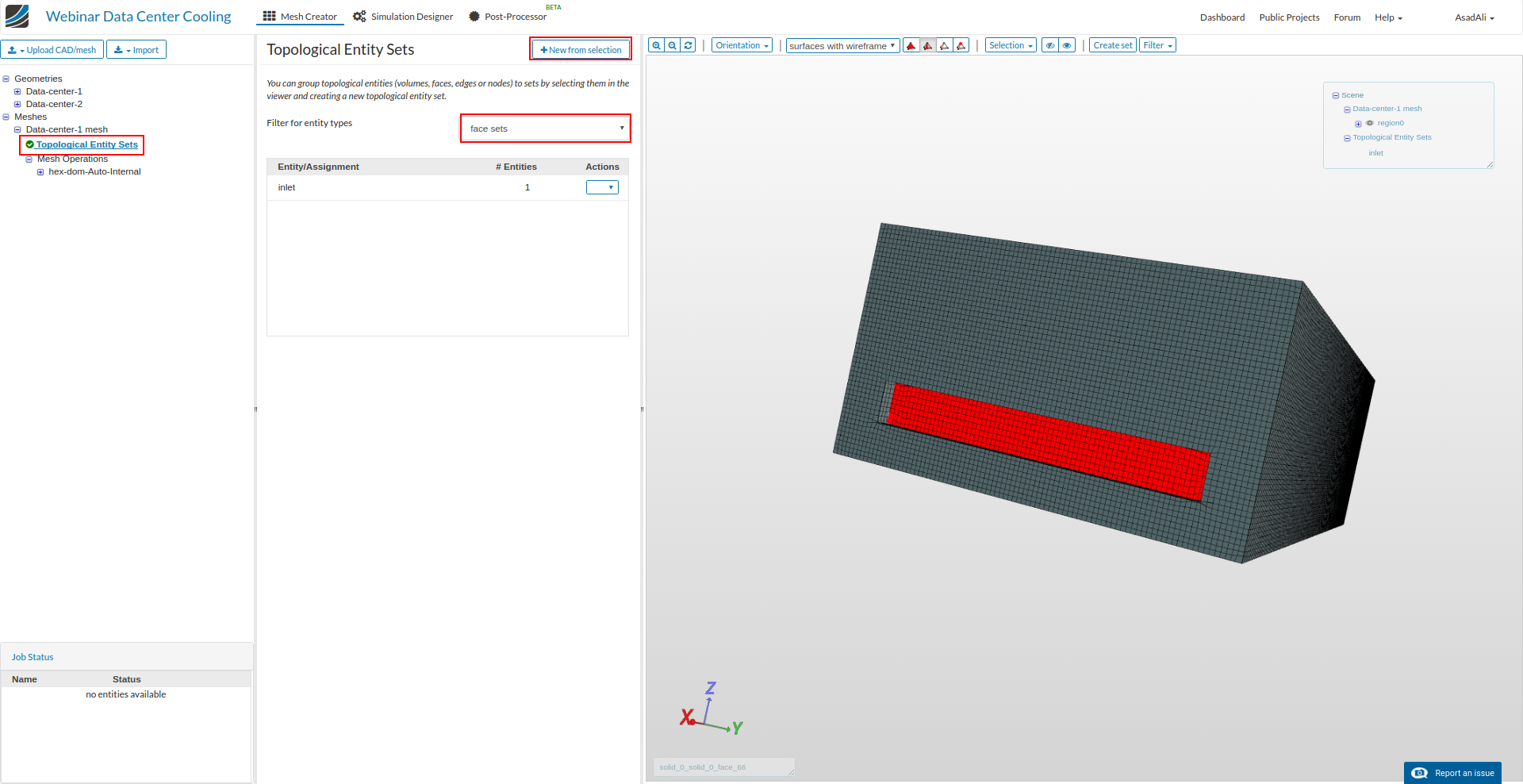
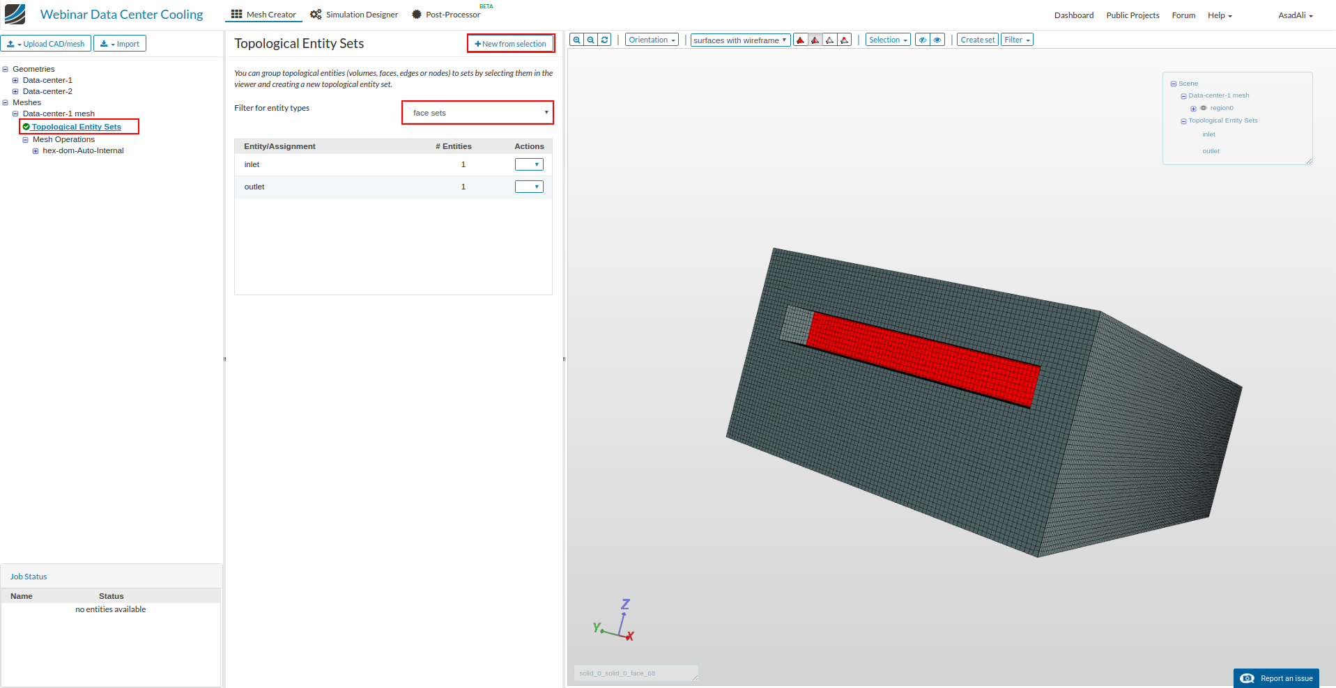
We have to create face sets once mesh is ready. Click on the Topological entry sets then select the inlet face and then press New from selection and rename it to inlet.
Similarly create outlet face set following the same steps.
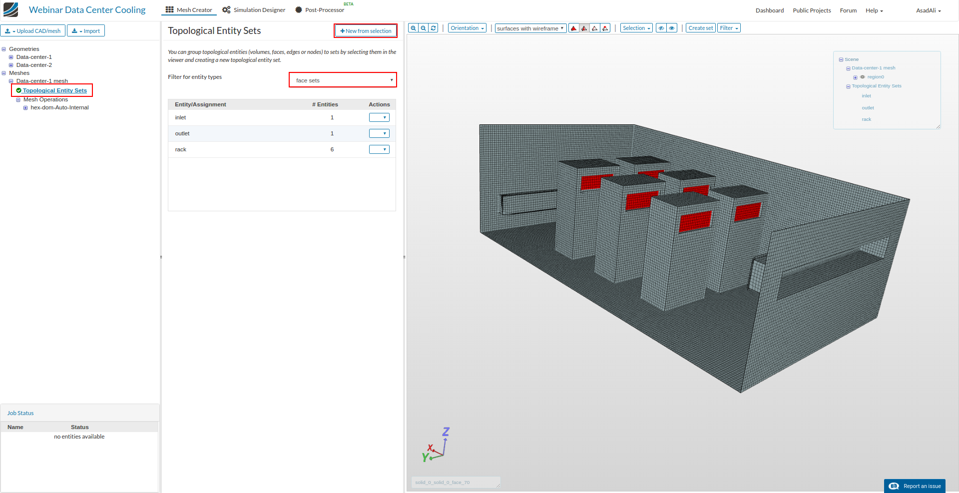
To create racks face, hide the side walls and then select the rack as shown in the image and create face set following the previous steps. Once face set is created, click on the “Selection” and select “Show all”.
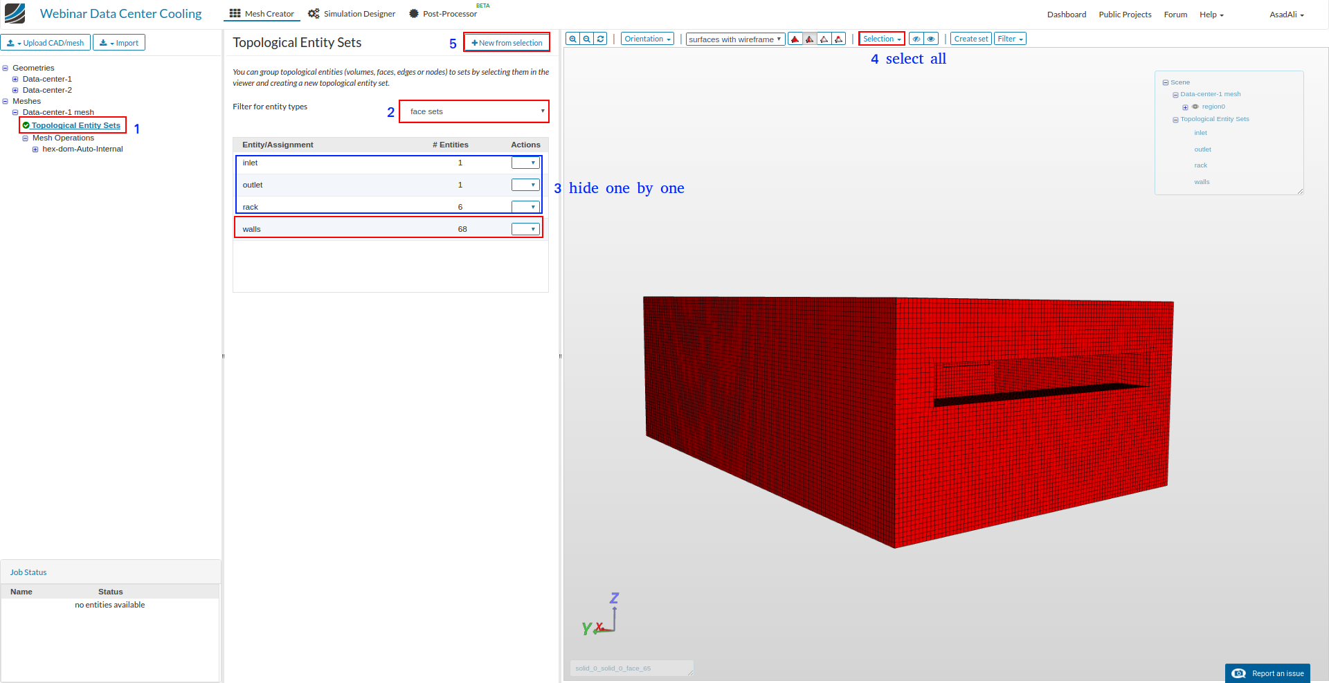
Now hide the inlet, outlet and racks by selecting and hiding one by one. Then from Selection select all and create face set by the name walls.
Simulation
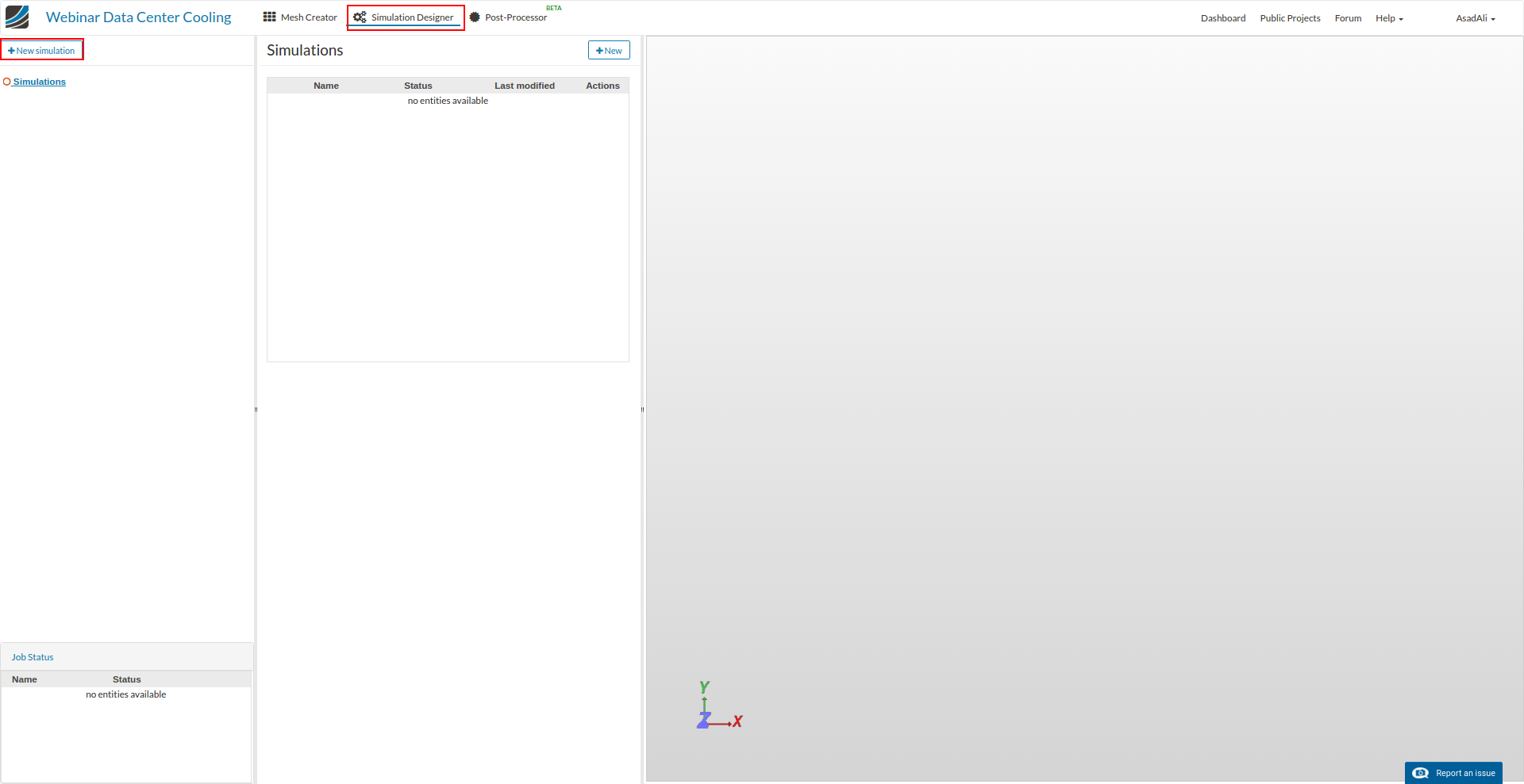
Move to the Simulation Designer and click New Simulation to create a new simulation setup.
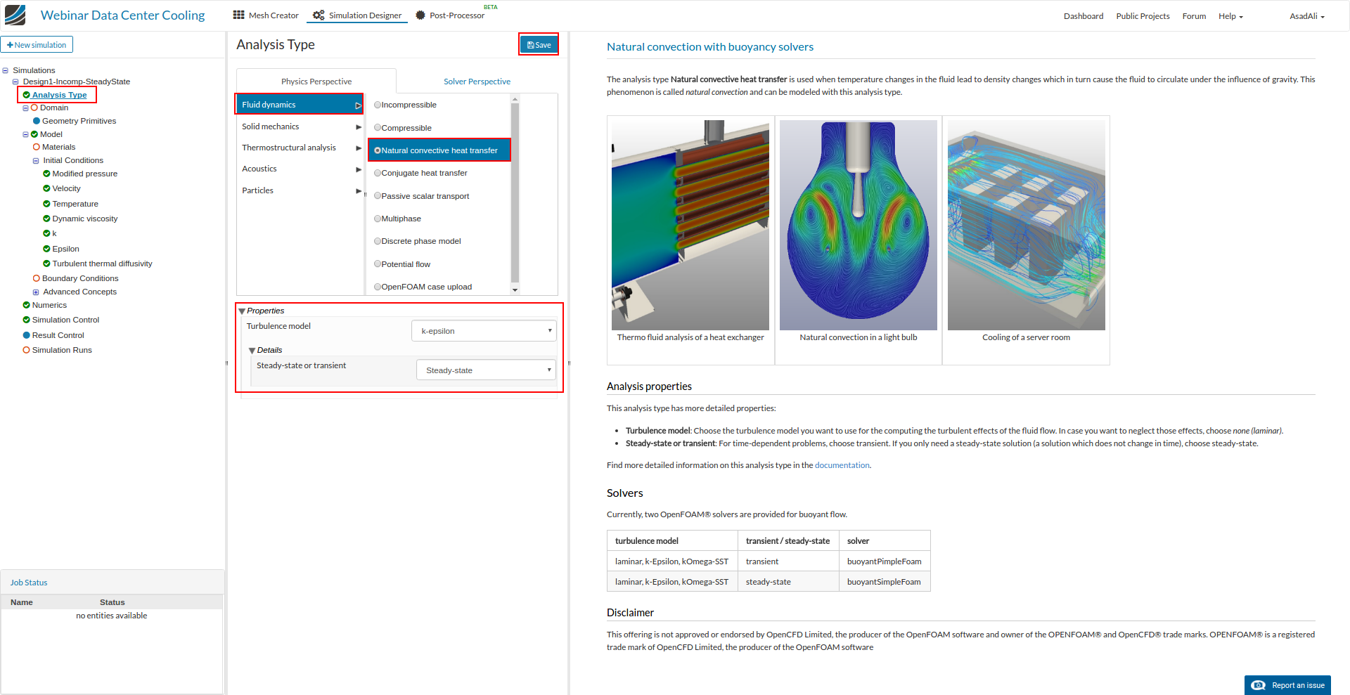
In analysis type select Fluid dynamics and Natural convection heat transfer. In properties select k-epsilon model for turbulence and steady state. Save the selection.
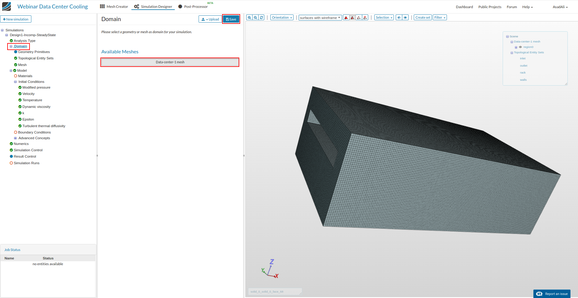
Noe to assign the mesh to the simulation, click on the “Domain” and select the “Data-center-1 mesh”. Save the selection.
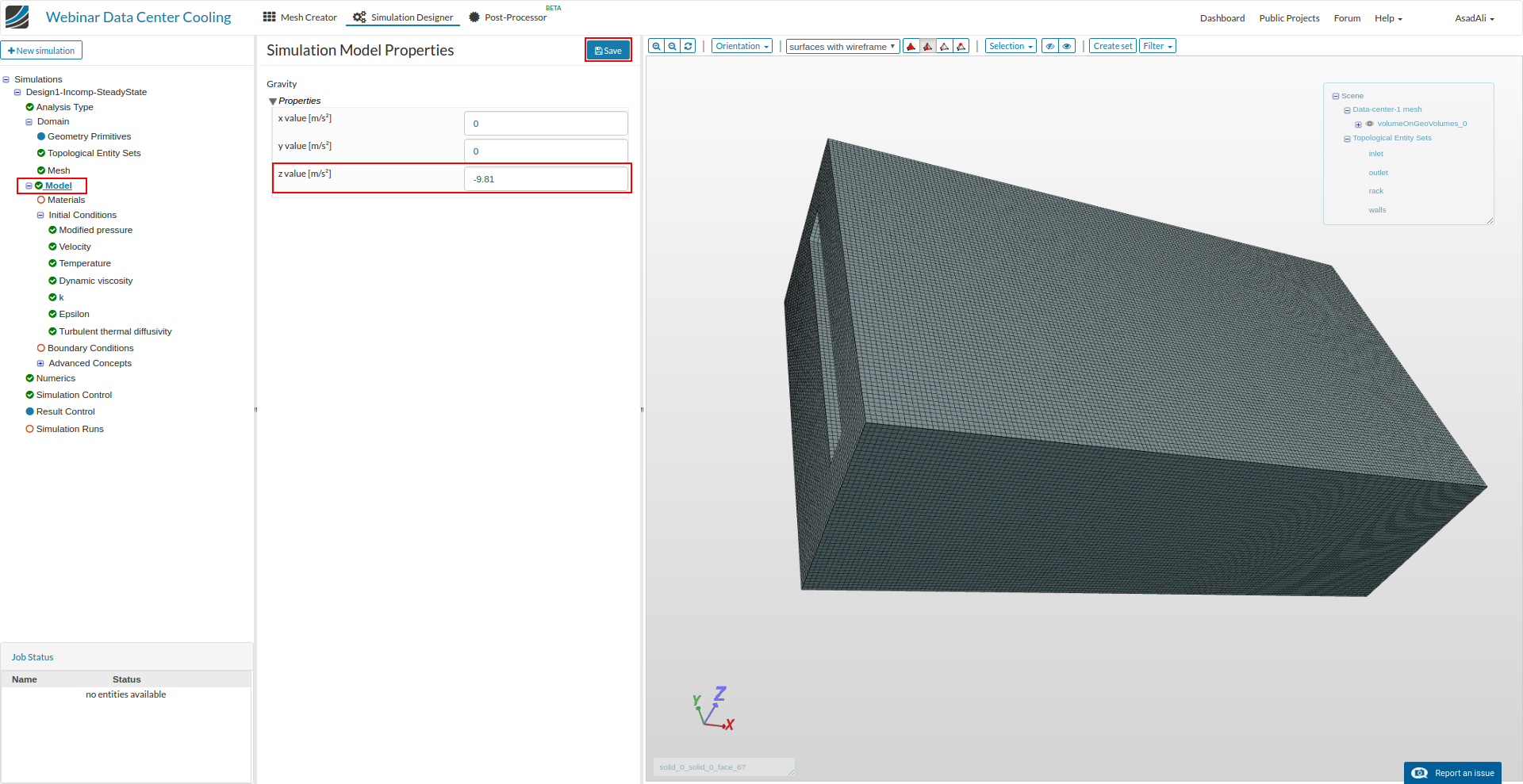
Now select the “Model” and define the gravity according to geometry orientation.
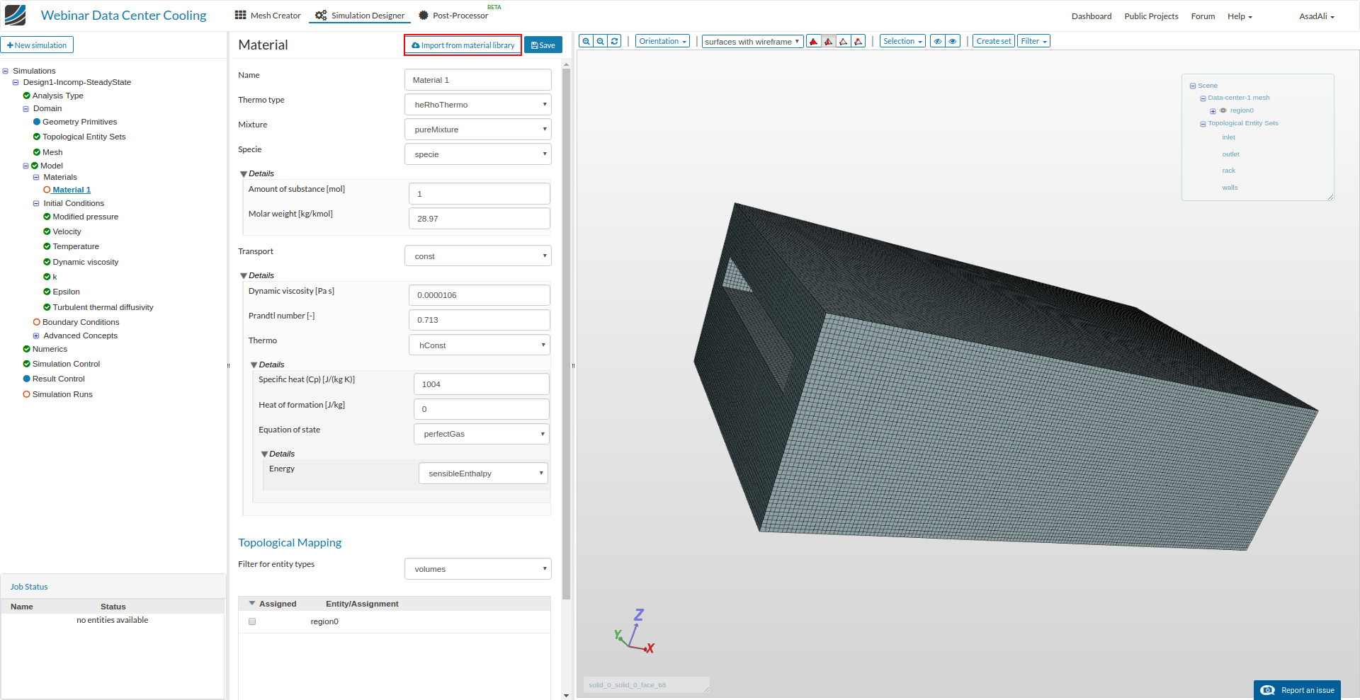
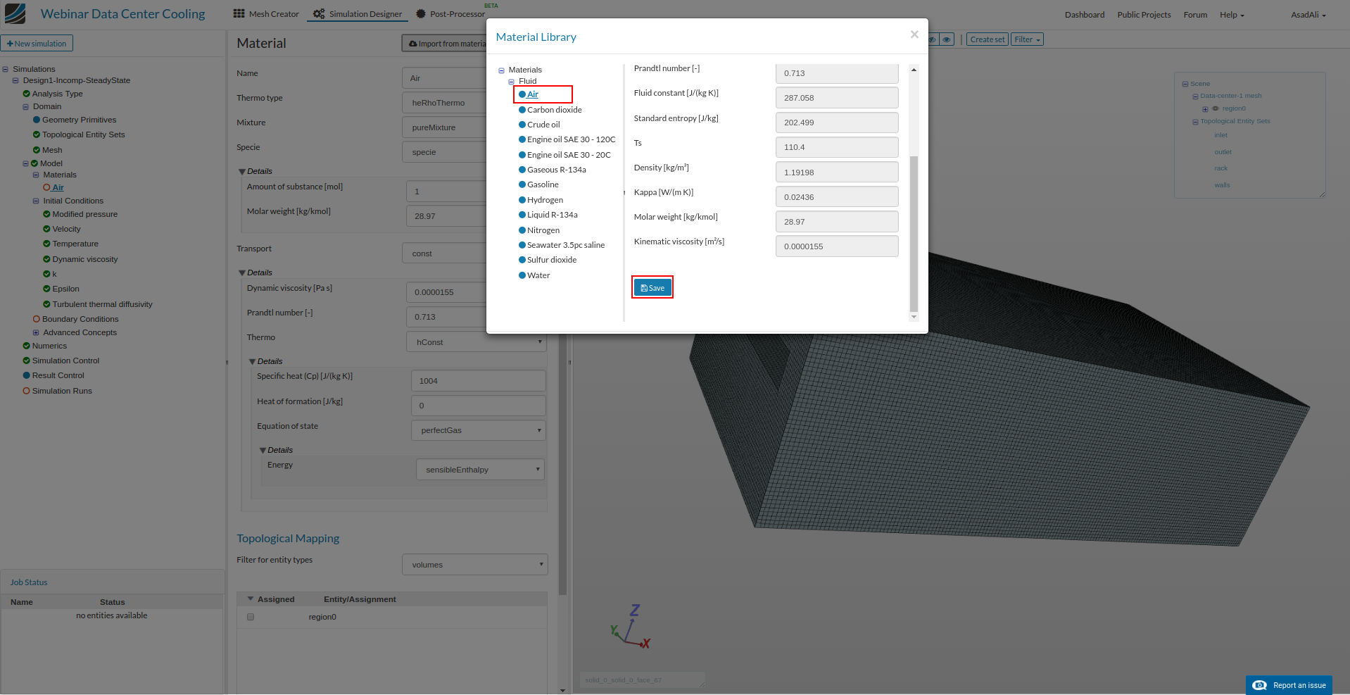
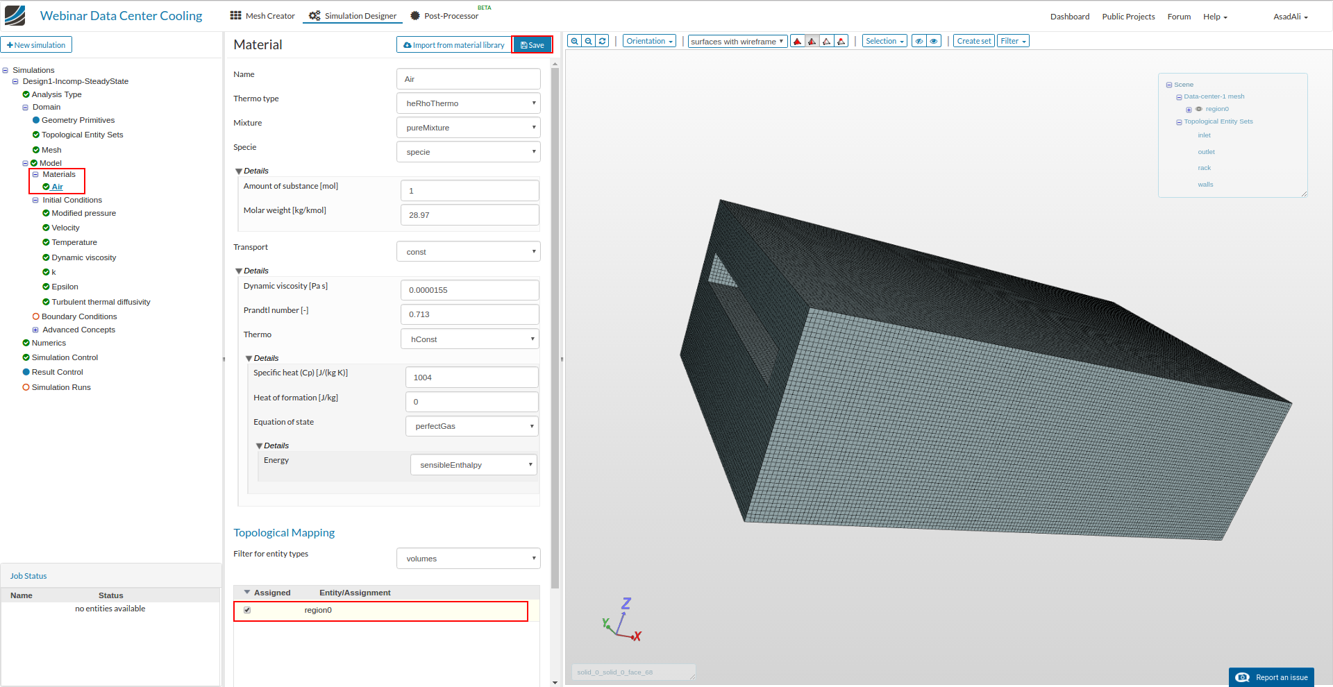
To assign the material to the domain, select “materials” and select new. Click Import from material library and from library select “Air” and save. Finally assign domain volume “region0” to the selection. Save the selection.

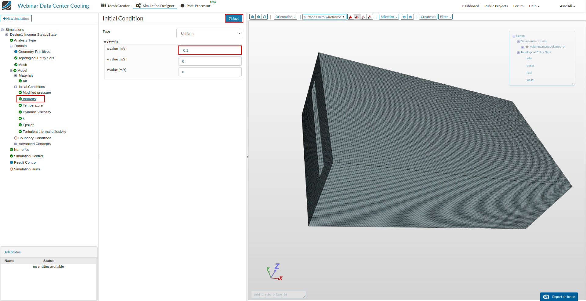
To change the initial conditions, click on the “Velocity” in “Initial conditions”, set the value accordingly and save the selection.
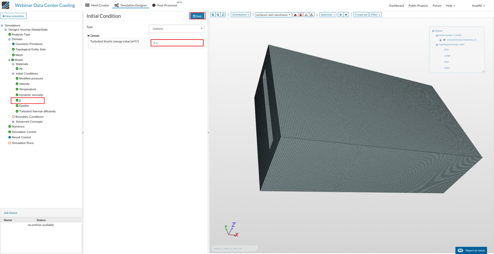
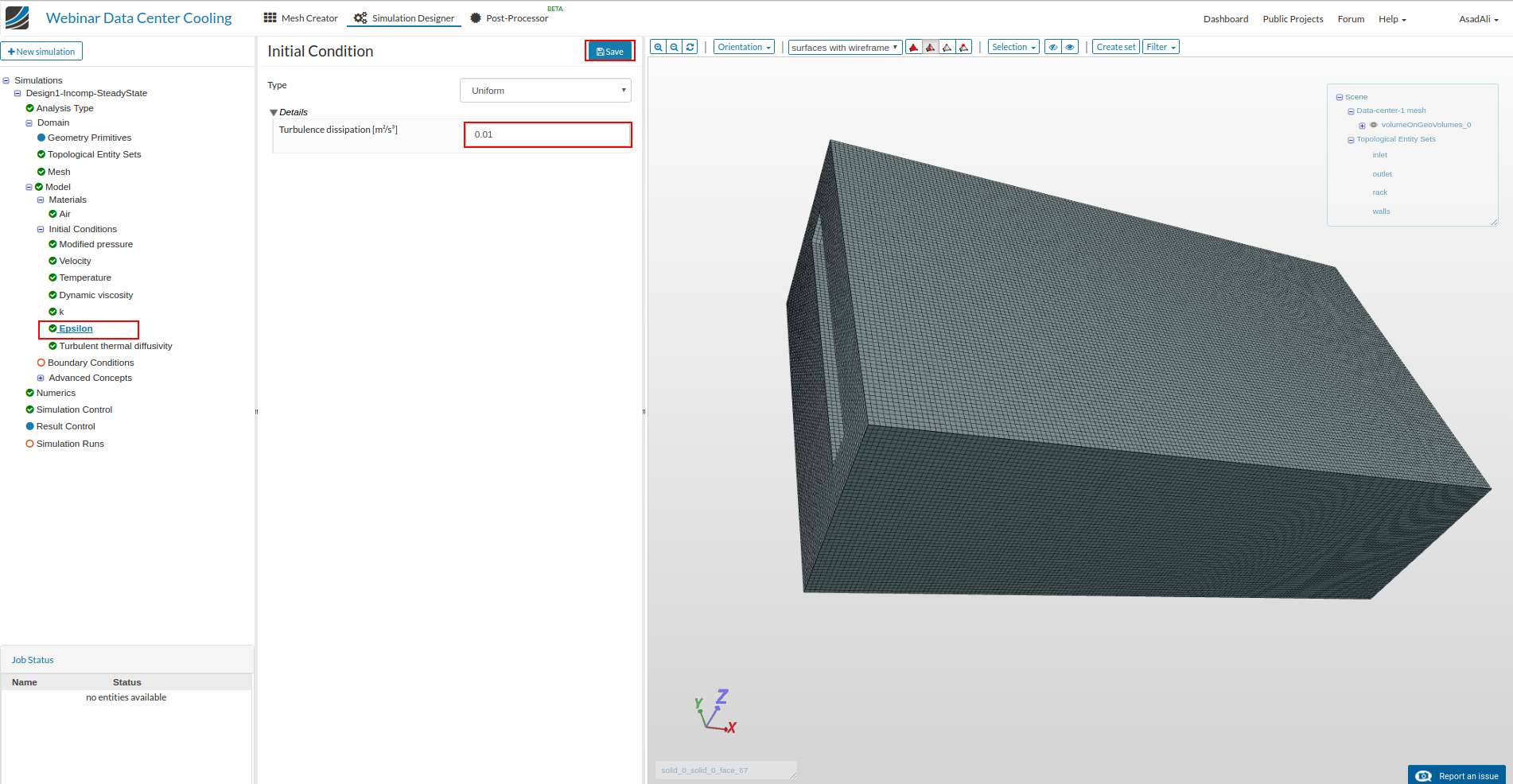
Similarly set the initial value for k and epsilon. Save the selection.
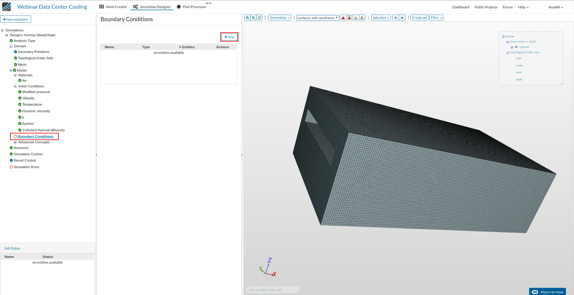
To add boundary conditions, select “Boundary conditions” and click New
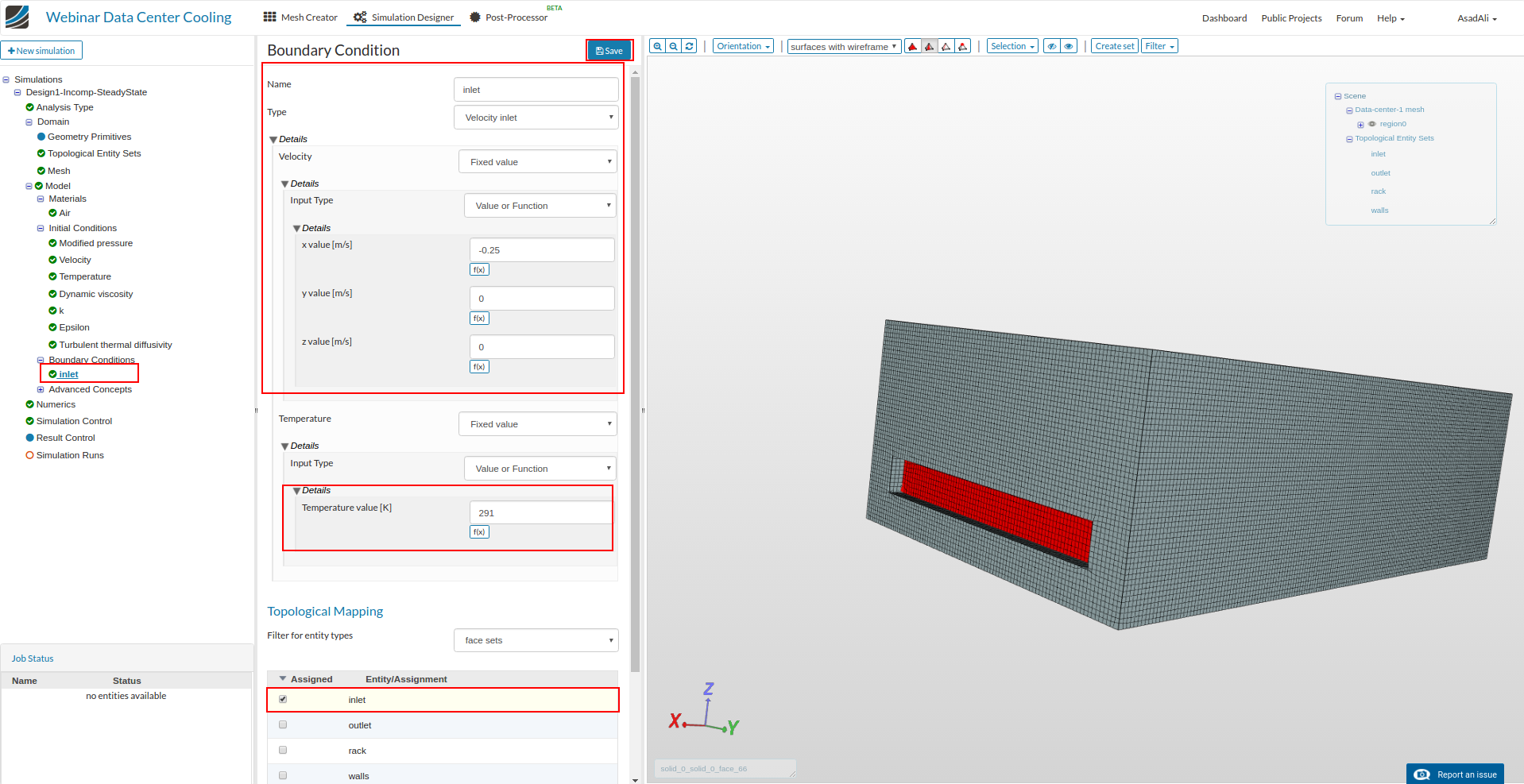
Rename the boundary condition to inlet and set the values accordingly, assign the “inlet” face set to the boundary condition. Save the selection.
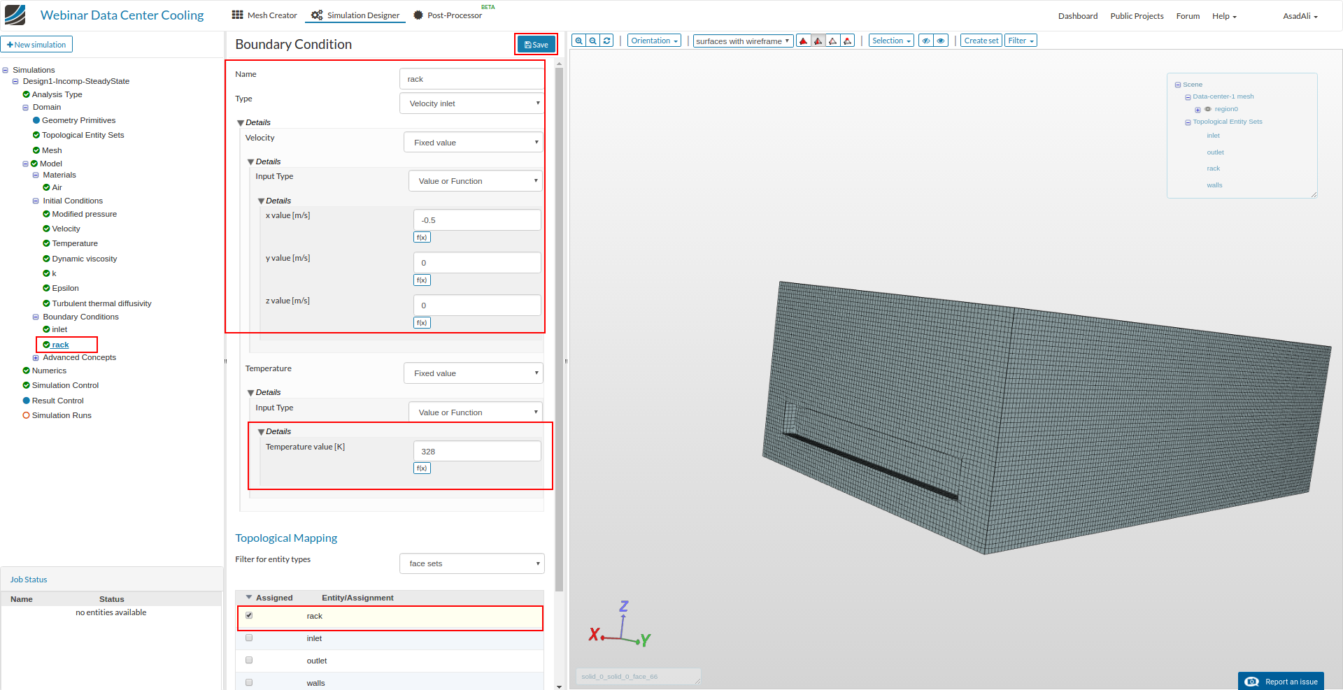
Add another boundary condition and rename it to “rack” set the values accordingly and assign the “rack” face set to the boundary condition. Save the selection.
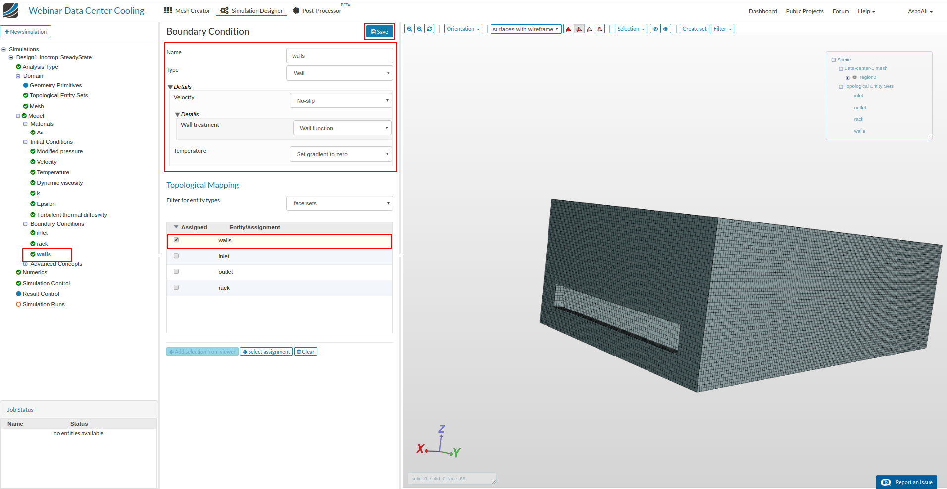
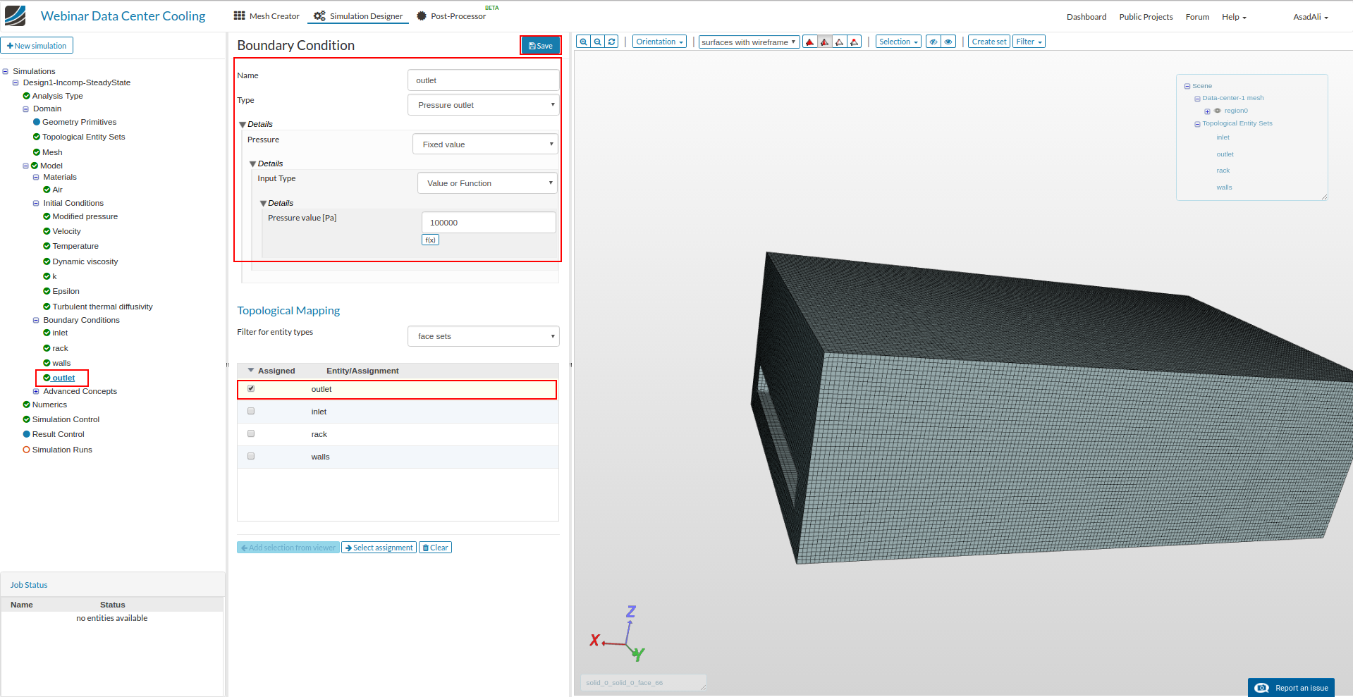
Similarly add boundary conditions for walls and outlet. Assign the corresponding face sets and set the values according the the images below. Save the selections.
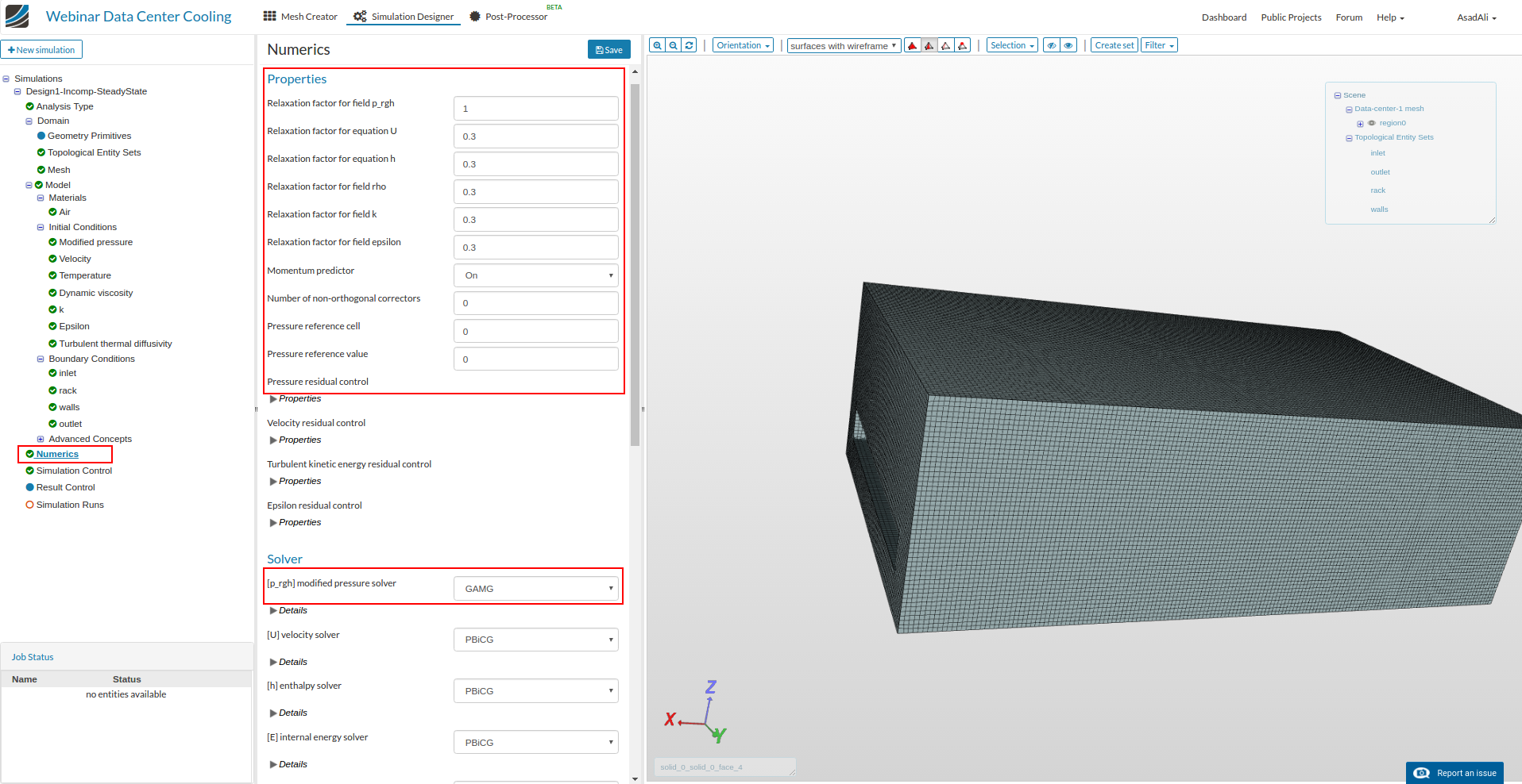
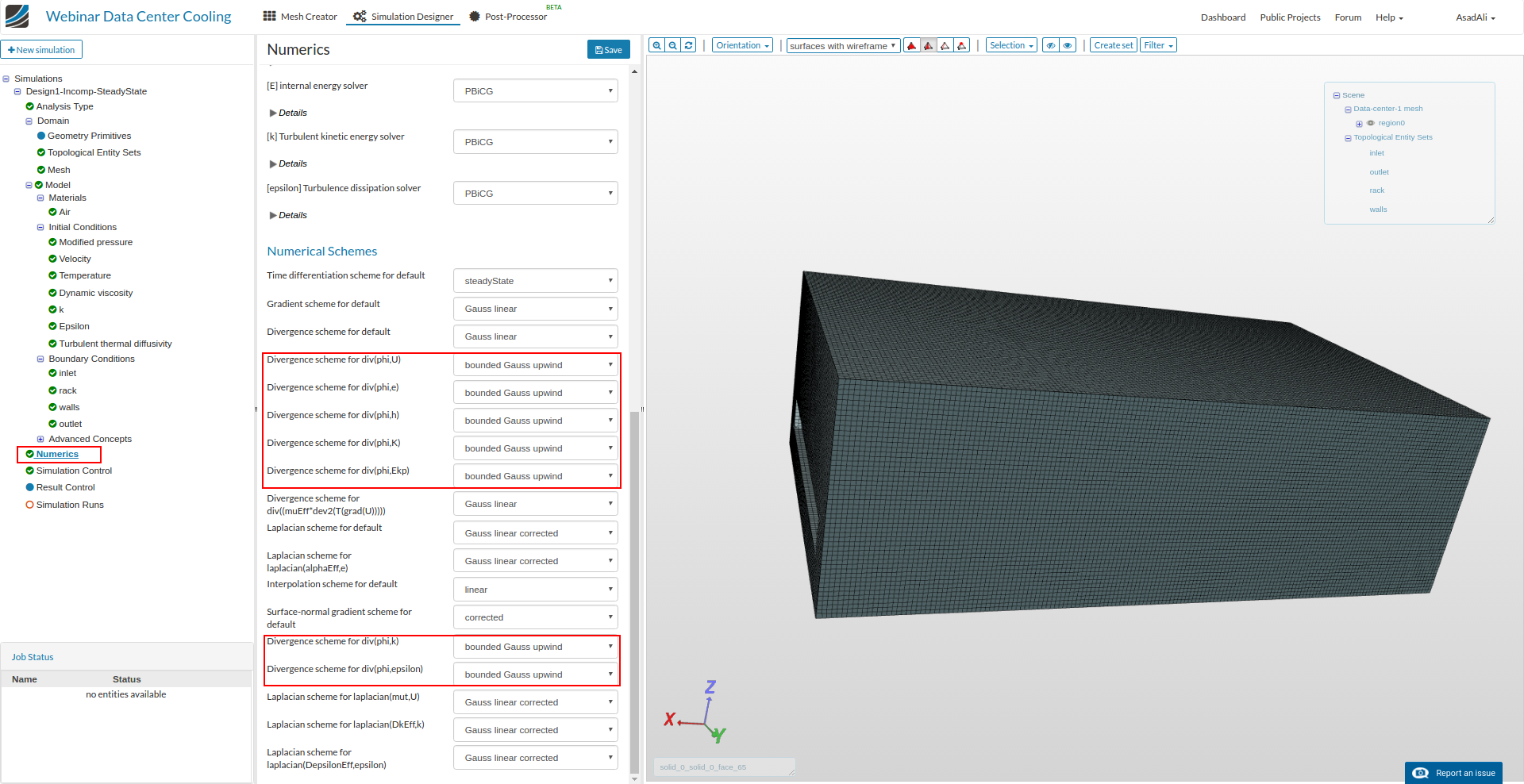
Click on the “Numerics” and set the solver parameters according to the following images.
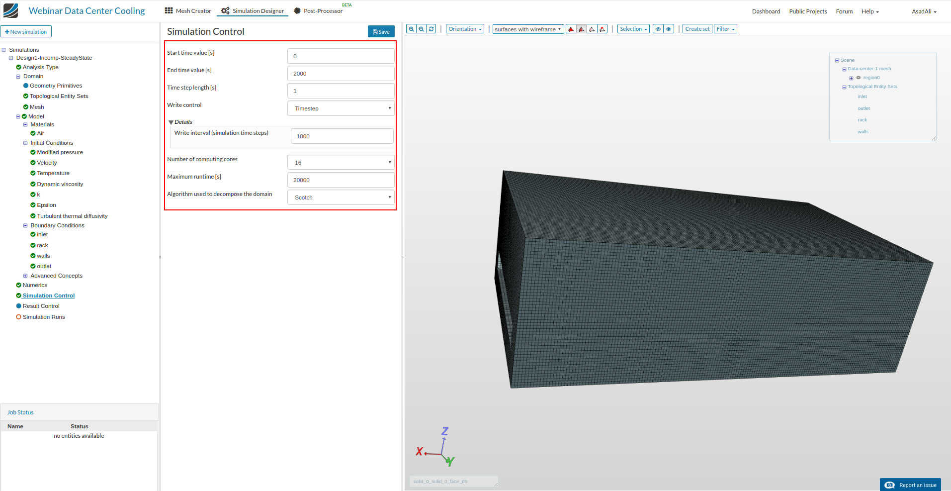
Now move to the “Simulation control” and set the values for the simulation.
Finally click on the New in the simulation run and rename the run. Click “Start” to start the simulation.