Hi everyone,
I’m new to SimScale and currently working on a project where I simulate the airflow generated by the propellers of a drone I use for aerosol sampling. My goal is to determine the height above the drone where the propeller-induced airflow becomes negligible (i.e., less than 1 m/s), so I can position my instruments accurately.
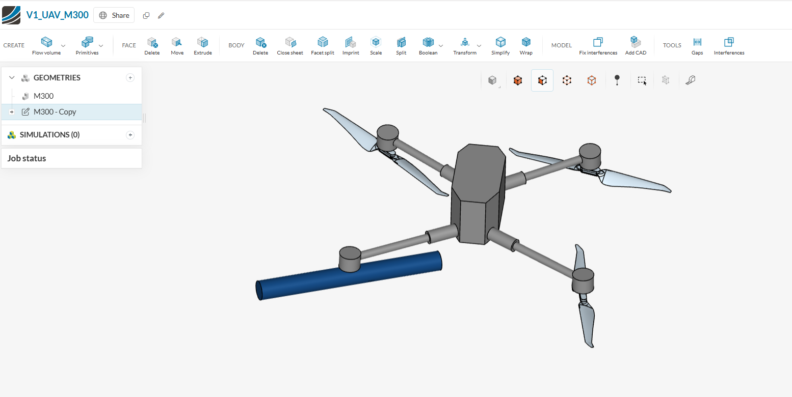
I’ve been going through the tutorials, but I’m running into trouble when trying to create the rotational zones using my own CAD geometry. Specifically, when I try to create a cylinder by selecting faces, the resulting shape doesn’t look right—it doesn’t match the examples and doesn’t seem to represent the propeller’s rotational area correctly.
Any advice on how to properly define the rotational zone for this drone?
(https://www.simscale.com/workbench/?pid=1452533486840011248&dcs=30178452-4e35-454f-afa9-0501481356c9)
Thanks in advance!
Christian