Correct BCs for Pump Simulation

In the context of simulating a pump impeller, I am wondering what would be the physically correct boundary conditions to apply, in order to be able to predict both flow rate and pressure elevation. My first try would be:

  • Incompressible simulation
  • Steady state
  • MRF model for rotating the impeller
  • K-Omega SST RANS model (wall functions)

Then it appears the question for boundary conditions for inlets and outlets. Looking at examples, I can see that the usual combo is velocity input + pressure output. But as I do not know in advance the flow rate for a given impeller RPM, how can I know the inlet velocity?

Now, what I did was to perform a simulation with pressure inlet + pressure outlet, both at 0 value, which allowed me to estimate a flow rate in the inlet face (by integrating the normal velocity) for a given RPM, then use this value for a velocity inlet + pressure outlet simulation. This failed in the first attempt with a divergence error, allegedly due to bad mesh elements (which I actually had), but I am not totally convinced, because of the doubts surrounding the BCs.

What I would like to discuss is the physical validity of the BCs, and learn what the valid approach or method is. Here are some questions:

  • If I specify the inlet flow rate and an MRF, then what work is the MRF doing on the fluid?
  • What new information or insight am I extracting from it if I already know the flow rate?
  • Can one correctly predict flow rate without any other input than RPM?
  • Is the zero pressure inlet/outlet condition even valid?
  • What if the input flow rate differs from the actual flow rate imposed by the impeller? What effect would this have? I know in real life the fluid would move the impeller, or cavitation might occur, but how does this physical discrepancy manifest in the simulation?

I will tag here the CFD Squad, but please, anyone contribute if you have experience or theoretical knowledge on the subject. I know the answer to this might turn out to be trivial or deeply theoretical, but I am sure I and many others will benefit.
1 Like

I should wait on more knowledgeable squad members, but they are in bed now, so I take this opportunity and (from experience) clarify few points:

MRF or rather impeller will show the mismatch if you report the ā€˜Forces and Momentsā€™ , on impeller. If Inlet flow matches impeller RPM, axial force will tend to 0.

You will still measure some moments and viscous forces on impeller.

You can calculate flow rate of impeller knowing the area of ā€˜activeā€™ zone of impeller. It is related to blades count, area swept , height and RPM. I suppose there an equation for that, but you can write your own afer few minutes of exercising your imagination. I would start with one blade. :smiley:

If I remember correctly, you start with Pressure Inlet > Total Pressure > 0, Pressure Outlet > Fixed Value > 0. Impeller will make necessary effort to move your fluid. You may have strong wake (or ā€˜destroying simulationā€™ wake), if you start with huge RPM right on. Remedy would be to ā€˜paceā€™ the MRF from 0 to 100 % RPM over ~50 - 100 first step. Observe convergence plot and forces on impeller.

Please use Result Control > Surface Data (area) on Inlet and Outlet. Miss match will show propeller lagging or or not. When Inflow and Outflow will match and MRF is rotating at right speed, axial force on propeller will vanish.

I hope it can help a bit. Happy simulation!

Cheers,

Retsam

5 Likes

Hi @ggiraldo,

@Retsam again has brilliantly answered most of your queries and I agree with them. Iā€™ll just add a few more comments where I can.

There are many ways to determine a required inlet value. While the easiest is inlet velocity, sometimes it is not so simple to define this as you have encountered. While Iā€™m unsure of the best way to obtain the inlet values, I would approach this by looking at the available inlet parameters and then based off that, from the manufacturerā€™s or empirical calculations with whatever data that is defined, decide on a input from there.

I believe your BCs are actually correct. However, accuracy is another thing all together. Unable to tell from here, will need the project itself to really determine the cause of divergence.

The MRF condition actually just applies a rotational value to the flow based on whatever geometry is defined within the MRF. If you apply a MRF to empty space, the flow will not be affected as there is no geometry to apply the value onto that will then influence the flow.

This ā€œapplicationā€ of rotational values to the flow is why I believe you are not supposed to use MRFs for transient simulations. Havenā€™t seen what happens if you do, maybe its time to try? :wink:

The other alternative AMI is more representative of actual rotation of the geometry. It rotates the mesh and geometry in it instead of simply just applying a value. Hence, more accurate and more computationally expensive of course.

Retsam has pointed out a valuable data point. From there, I believe it is possible to discern forces acting on the blade which can help in determining say the fatigue life of the blade or further modal analysis in FEA. From a CFD standpoint, the efficiency of the blades through the pressure distribution across it, the behavior of flow around the impeller, the presence of pressure/velocity anomalies throughout the internals of the pump are all very valuable data points that can be obtained.

I believe Retsam is referring to blade element theory. Its quite a bit of math, quite annoying :stuck_out_tongue: If you can keep within error of margin the empirical calculations against that of the simulation, that would be brilliant.

I was about to type about a possible continuity error but thinking about it again, it is dependent on your BCs. If you impose a very strict BC like a fixed inlet flow rate and a fixed outlet flow rate, unless your geometry is perfect like laminar flow going over a sphere, you will have continuity errors as the net mass flow at the inlet vs the outlet will differ should there be any discrepancy from any irregularities in flow.

That is why we always impose a pressure outlet 0. This allows the flow to effectively compensate for any continuity errors as the final outlet does not require an exact solution, rather one that completes it, much like a simple equation with 1 unknown.

I hope that kind of sheds some light as going back to your use case, if your inlet/outlet BC does not impose an exact solution that may give rise to a continuity error, a difference in input flow rate vs actual flow rate will still work and give data outputs as to what Retsam has mentioned.

Would be interesting to see what other effects could happen should this occur.

Hope I was able to provide some help!

Cheers.

Regards,
Barry

5 Likes

@Get_Barried: MRF zone is an inspiration source for many hypothesis. :thinking:

I was also convinced that MRF zone / no MRF zone boundary is harmless. When MRF zone is excessively large in relation to rotating geometry, it could cause problems. I had a tiny rotating cylinder and huge MRF zone (but smaller then BMB). Rotation of cylinder was set on progressive slope and (incompressible) simulation was breaking when peripheral speed for MRF surface (far from cylinder) reached 180 - 190 m/s . Visualisation of results confirmed that empty MRF being very activeā€¦

If somebody wants to look that strange effects, the project is here: Magnus effect and Rotor propulsion simulation by Retsam | SimScale.

From that moment on, I was suggesting to use as tight MRF zone as possible. It may cause meshing problem with some geometry (if in vicinity to other non rotating elements) , but actually works quite well. However in case of fan / impeller rotating in an enclosure, better tactic is to make MRF touching or even ā€˜mergingā€™ with enclosure and define ā€˜moving wallā€™ BC on the enclosure neutralizing rotation of MRF.

Cheers,

Retsam

1 Like

Next time I will think twice to propose calculation shortcuts, this time I will go with a simple example.

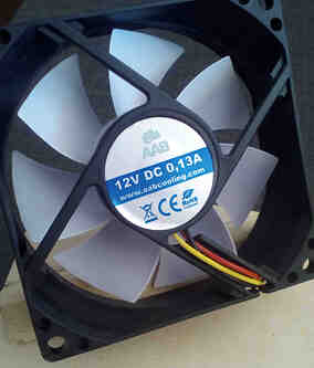
I only have on hand a PC fan, 80 x 80 x 25 mm, rated at 33 m3/hour. Pump impellers have complex shapes and ducts, Iā€™m on easy path. Letā€™s do it:

Fan diameter: 74 mm. Fan area: 43 cm2
Hub diameter: 33 mm. Hub area: 8.55 cm2
Active fan area: 43 - 8.44 = 34.46 cm2
Fan height: 17 mm
Fan active volume = 34.46 cm2 x 1.7 cm = 58.58 cm3.

One blade over one seconds push 58.58 cm3 of air.
Seven blades will push 410 cm3 of air.

Fan rotation speed is 1600 RPM. 1600 / 60 sec = 26.66 rotation per second.

410 cm3 x 26.66 = 10935 cm3 per second.
10935 cm3 x 3600 sec = 39.365 m3 / hour.

Fan is rated at 33 m3 / hour.

33 m3 / 39.365 m3 =~ 84% blades efficiency.

Now, knowing that no blade is perfect :wink:, we can use our calculated efficiency to all similar type of fans and discover volume of air it will pump over an hour.

Cheers,

Retsam

3 Likes

Hi @Retsam,

So the tiny geometry was outside the MRF but strange flow behavior persisted?

If you meant a tiny geometry within a MRF that causes these large flow irregularities, then that is to be expected as the MRF implementation best practices do call for as tight a MRF zone as possible to maintain accuracy. As for the math on why this is so, I am again, unsure. Guess it might do me some good to do some light reading!

Cheers.

Regards,
Barry

1 Like

Yes, within MRF. Near all examples of MRF zone Iā€™ve seen were ā€˜too largeā€™ in my opinion, so, experimenting, I found the proof that it should be tight.

Cheers,

Retsam

1 Like

Thank you so much @Retsam and @Get_Barried for your insights, I was able to understand it a little bit more and come up with some ideas of changes to try.

I will eventually make the project public so everyone can have a deeper look, but not yet. Will update here when so.

1 Like

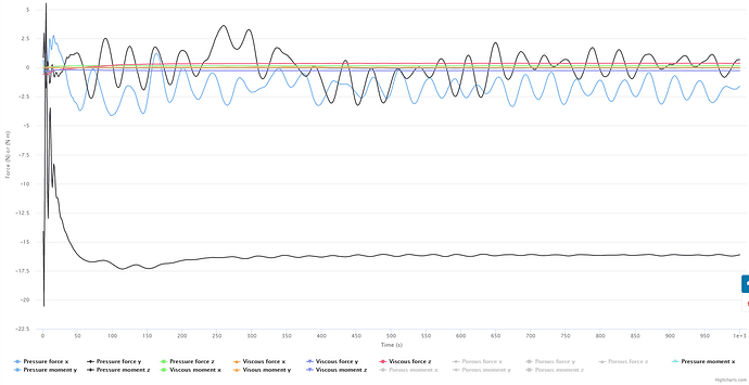
What do you think about this plot of forces on the impeller blades? @Retsam

@ggiraldo: Looks like simulation converged @ about 200 steps. For oscillation (on momentum?) I do not know, but may be linked to Inlet / MRF matching ā€˜residualsā€™. What is your take on it?

1 Like

@Retsam: I have seen this oscillating behavior on steady state solutions before, and to be honest, do not know the cause.

The oscillating variables are X and Y pressure force components, by the way.