Normal if we want to simulate the cooling of an object by forced convection, we create a mesh of air around the object and provide the air with a velocity. Imagine we have a parallel shaft with cooling fins (and so therefore it does not have a uniform diameter throughout), which undergoes forced convection. How can one model this scenario? Modeling it as a linear air flow would not be accurate.
The only idea I have is to create an air mesh in the shape of a doughnut around the shaft, with a very small slice missing and then define an air flow within the doughnut. Are there any other options (I know I could also setup a regular heat transfer simulation and chose a convection coefficient but that is only as accurate as the convection coefficients I choose, which would be a guesstimates)
Maybe I did not get it from the text but do you want to cool your components actively or passively? Also if you have a first draft or sketch of your problem, that would help a lot. First guys that came into my mind thinking about this problem were @Retsam as well as @DaleKramer who have been dealing and tinkering with CFD simulations for quite a while. Guys, any input from your side? Also tagging the @cfd_squad as always to get more impetus from the others as well!
To cool the rotor by forced convection i.e. a forced airflow but rather than a fan, it is the rotation of the rotor that causes relative motion between the rotor and air. I understand that the mesh can not be rotated in the conjugate heat transfer so I need some other way to create a circular airflow around the rotor. Is there a method to define vorticity within a closed volume of air?
Thought that you wanted to combine both cooling mechanisms. There is a way to introduce vorticity with so called momentum sources that are available in the advanced settings. They are virtual areas within the flow that force the fluid to move in a particular directions. In that way you do not need to directly model the fan (mesh the blades, add rotating zones). Example project: Actuator Disk.
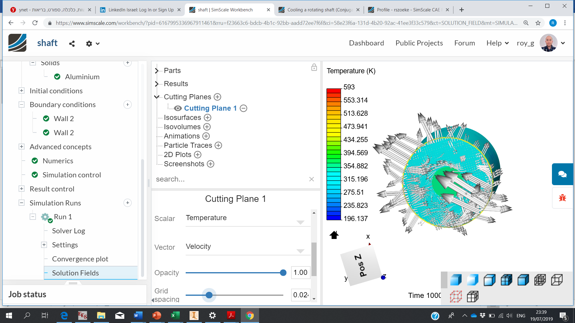
I tried adding a momentum source to achieve a rotating airflow around the shaft. I used velocities of 5 m/s for x and y which are the in plane velocities and 0 m/s for the perpendicular velocity. As you can see the vector field of velocity is a mess. Do you have any ideas?
I see, looks odd Share your project here in the comment section and make sure it is set to public. I will have a look at it at the weekend and tag my colleagues @cfd_squad here who might add their thoughts to that as well.
To see the results you will need to setup an animation on the final timestep (like I posted last night regarding the possible bug)
Enjoy your weekend too (I am taking my daughter to the petting zoo this weekend, she is 1 and a half years old. When she is a little older I will introduce her to using simscale )
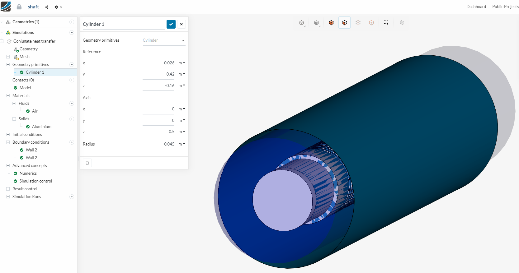
An idea would be not to use the whole outer domain but maybe work with the geometry primitives (cylinder with the length of the shaft), as depicted below:
However this is just a first thought and might either be solved completely different (and more easily) or might need some more workarounds Already asked if we have anything planned regarding MRF for CHT!
With that Momentum source which is ‘Shaft_negated_solid3’ you blow 7.1 m/s wind in one (perpendicular to the shaft) direction, but it goes nowhere. It cannot even rotate. I’m afraid Jousef solution would not change a lot in that respect.
Is your shaft really in a closed cage (and heating the air around it)?
Or is the surrounding air evacuated while moving in shaft vicinity?
Anyway, in order to simulate air rotation in that cage, you need to define small ‘Geometry primitives’ in that cage space (3 or 4) and make them blow the air at appropriate angle toward shaft surface.
But I suppose it would be better to evacuate that air by defining pressure inlet / outlet and slightly modify the Momentum sources direction along Z axis.
Thank you for your input, I did consider building an air volume that is similar to a wheel o f cheese with a hole in the middle (for the shaft) and a small slice missing so that I can define an inlet and outlet (is that what you meant?) but have not got round to trying it yet. My aim is to approximate the effect of the shaft rotating by other means since there is no option of MRF for conjugate heat transfer simulations. I set a convective boundary condition around the air volume so that the heat can escape but I suppose that since I can not simulate air leaving the volume by natural convection, the air volume needs to be large enough that it can be considered infinite. On the other hand if I add an inlet and outlet as you suggested then the cooling effect may be slightly exaggerated as the replacement of the boundary layer air will occur much faster than in reality.
 Share your project here in the comment section and make sure it is set to public. I will have a look at it at the weekend and tag my colleagues