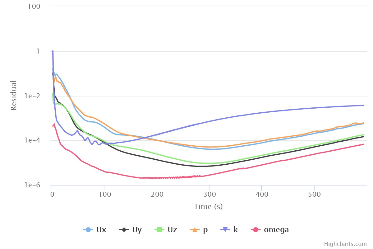
This is my convergence chart from my most recent sim. I have been modeling a loose representation of an FSAE style rear wing to learn how to use CFD to improve a design. I have finally started to get a decent mesh going on my past few versions. Oddly on this version all I did was shorten the width of the model to a more realistic size and all of a sudden the convergence gets a little funky and the results are skewed. Any Idea on what would cause this?
I am talking about V46RS. Here is the link:
I made sure to correct the mesh for the change in size but none of the other settings changed. I would appreciate any other eyes and help. I apologize in advance for imperial units, I only use them because that is what my team uses.
I am not 100% sure what the problem could be but one guess is that you didnt let the simulation run long enough to stabilize the values. I havent checked your other sims but im guessing you also ran them for only 850 iterations. It could be that the change you made requires a longer solving time (for whatever reason) and the residuals will soon flatten out.
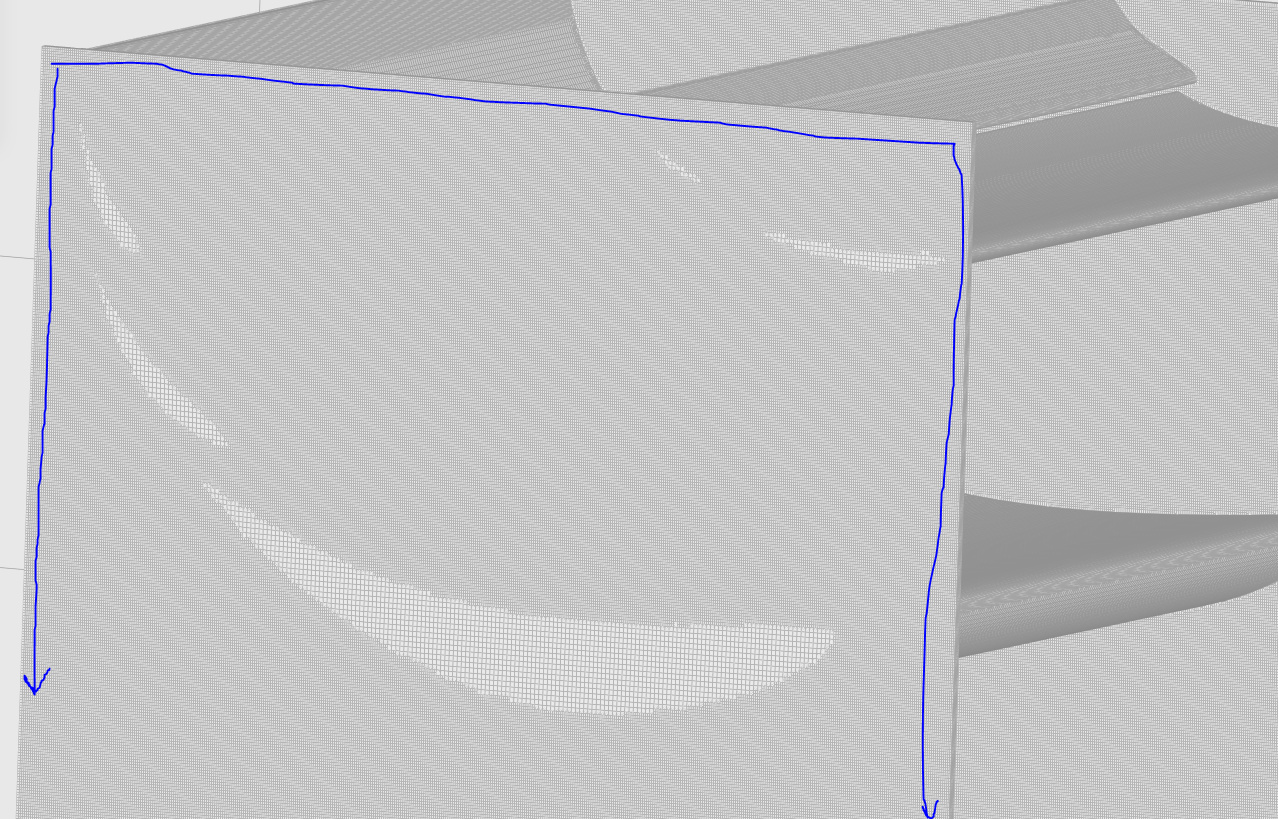
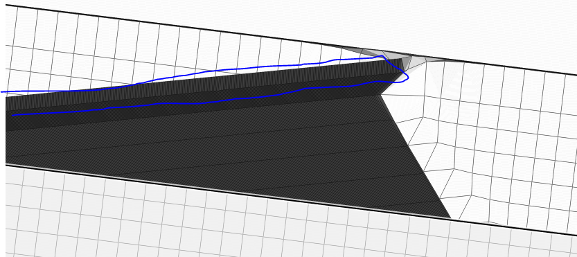
Another reason could be the sudden cell level increase in proximity to your wing. The sharp increase in cell size as the flow reaches your wing is not the best for result accuracy and could be causing the convergence issues.
Some other general suggestions for what i noticed:
I would either increase your inner region refinement cell level or add a distance region refinement to your surfaces to aid in a smooth cell size transition.
i would also add a region refinement behind the rear wing to capture the wake flow. This will also help with result accuracy.
Finally i would check your Y+ values as this is critical when using wall functions to measure results in the log-law region.
I appreciate all the tips. I had one that I ran for the full 850 iterations on this wing and it had really weird results and I could see the convergence on this run was doing the same thing so I stopped it early to not lose too many more core hours. And I originally was running my sims for 1500 iterations and they looked to be converging long before that so I figured I could try to save some core hours by not running it for as long.
What can I do to decrease that sudden cell increase in cell size close to the wing? Adding refinements? Change the ones I already have?
Could I extend the Cartesian Box I already have further behind the wing as well as raising that region’s refinement level to take care of both problems? Or how should I best go about doing this?
Yes stopping a simulation when convergence is met is always a good idea.
I would personally do the following:
Unless you are doing a Yaw or roll study, you can cut the entire simulation in half to save a lot of resources. Simply have the bounding box intersect the geometry in the middle.
the outer edge of your endplates are the only areas that need to be refined higher to get good mesh conformation. The entire middle section can be coarser. So you can split the outer region in CAD into a seperate solid so that you can apply a different refinement to the middle or edge
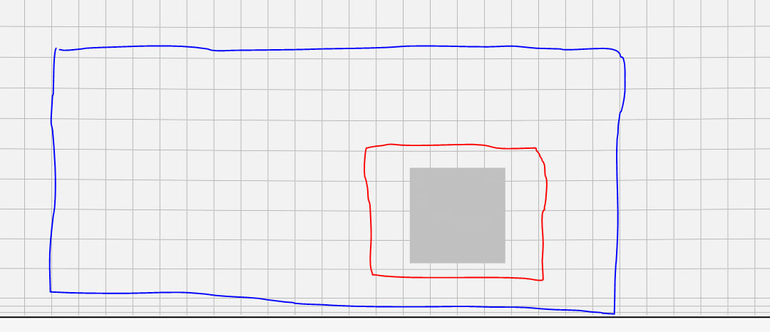
For region refinements i would have a higher refinement box around the wing (red) and a lower one for the wake region (blue). this allows the cell increase to be smoother
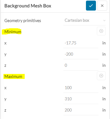
Could you look over my setup of the mesh for a half geometry mesh? The estimated cell count looks like it might be as high as a full-sized mesh, I just want to know if there are any alarming issues with my setup.
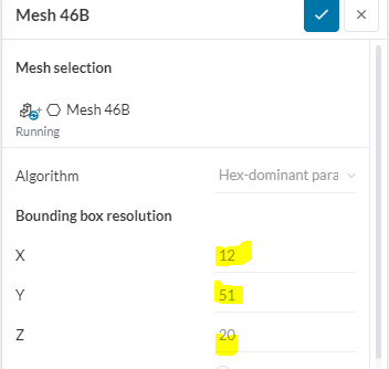
have you calculated the bonding box size (first pic) VS the amount of cells in each direction (second pic)? The best thing for HEX meshes is to have all directions equal. As in all faces of the cell are the same size.
It seems you got the Endplate and Wing surface refinement levels mixed up. You currently have the endplates at a higher refinement level (level 8) which means the cells are smaller (its a bit confusing)
You can always check the physical cell size of each level based on the starting level 0 cell size, which is what you designate based on the bounding box/cells in each direction.
Simply cut each level in half
CELL LEVEL
Meters
Millimeters
Level 0
0,013
13
Level 1
0,0065
6,5
Level 2
0,00325
3,25
Level 3
0,001625
1,625
Level 4
0,0008125
0,8125
Level 5
0,00040625
0,40625
Level 6
0,000203125
0,203125
Level 7
0,000101563
0,1015625
your region refinement sizes / cell levels look good
I am still concerned about your boudary layer settings. I dont thing these will give y+ values in the log law region. I assume you are trying to measure using wall functions´
For the most part, I have figured mostly everything else out. My most recent run on V46RS has been the best one I have ever had. I had my best mesh so far, though still not perfect; it only had 1 illegal face in it. The only thing I don’t understand is how to set up my boundary layers so that it outputs a specific y+ value, and fixing mesh errors like edge-ratio and non-orthogonality cells.
Y+: I have done a lot of reading and completely understand the wall model method and the full-resolution method pretty well in concept. I just have not found anything that actually explains how to determine this in mesh setup.
Non-Orthogonality: My most recent sim is the lowest it has ever been, but it is still maxing at 83 and not well below 75 as it should.
Edge-Ratio: The same problem with edge ratio except it is way worse with it being around 250 or so I remember correctly.
For finding Y+ values you need to use a calculator. I use THIS
if you are staying with just a rear wing sim, its small enough where you can simulate the viscous sub-layer, so shoot for a Y+ less then 1. If you plan on implementing a half car sim then go for the log-law region so that you wont have memory issues when applying your methodology to the whole car.
The max Non-ortho values you receive should be as low as possible. However, just the fact that there is a geometry in the domain means that the cells have to distort around it. This is normal and you will never get completely rid of non-ortho cells because your geometry is creating them. A max of 83 is fine, most of my meshes have 89 as its difficult to get every bad cell. Only when you have a lot of non-ortho cells or when a few are at 89.9 then you need to worry.
You can use the Mesh quality feature and set the iso volumes to show non-orthogonality. this will allow you to locate the bad cells and fix them in CAD with a chamfer or fillet. However, if the CAD changes effect the performance of your wing then you must either live with the non- ortho or try and remove them through the mesh settings. I have outlined a few of these topics in my article HERE