Thank you for your help @jousefm,
but I think your changes with the boundary conditions don’t resemble what we are trying to simulate.
My copy of your project:
But lets start with the material properties: I just took the materials from the library, the values differ only slightly from the ones you used, so it has hardly any impact. Especially not causing a temperature of over 4000K. (I assume changing the density from copper to 2700 kg/m^3, which is the density of aluminium, was a mistake. But it should only cause the chips to heat up faster and have no effect in a steady state anlysis, right?)
The boundary conditions:
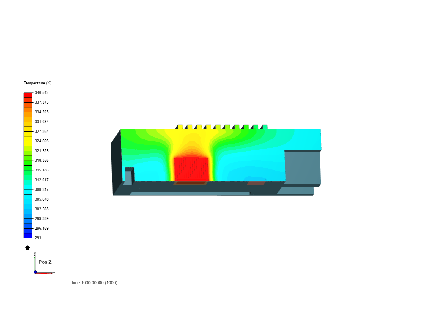
The idea behind this simulation is, that two chips have a certain power loss (because of elcectrical resistances), which has to be transported away by the circulating air. The “Absolute power source” in the chips is supposed to be the only energy source in the simulation and the air the only means for the energy to leave the system (if we ignore the optional boundary condition “External wall heat flux” for the exterior faces ). The initial conditions, which set the starting temperatures of the chips and the heat sink to 363K or 316K, should only cause faster convergence and are not necessary.
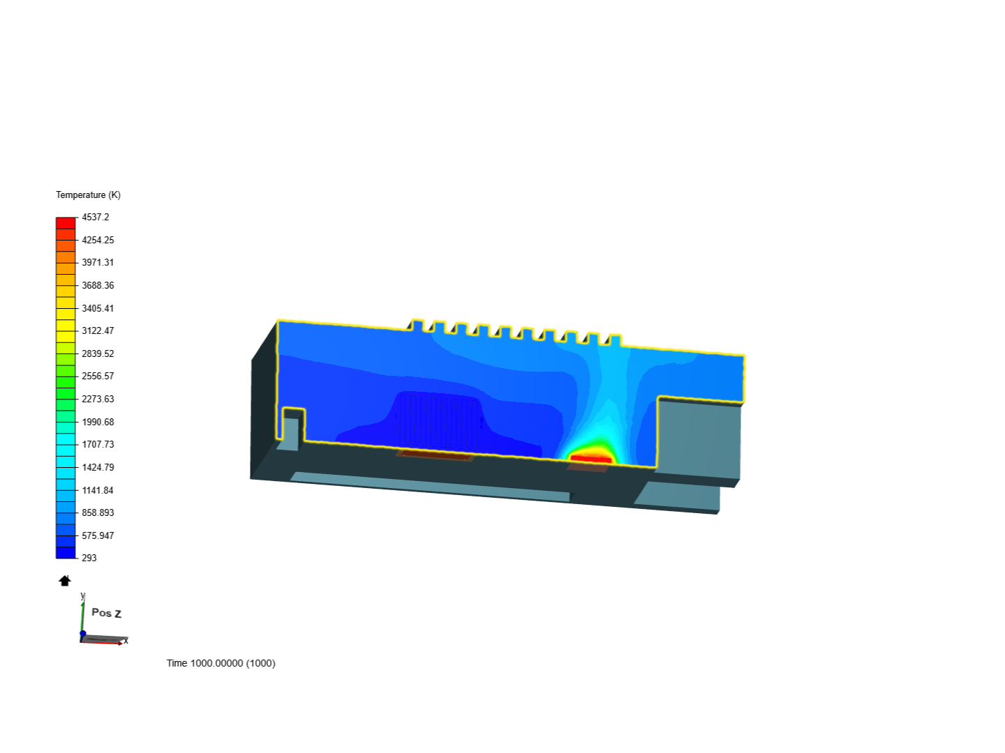
But your (the 4.) boundary condition “Copy of Wall 3” gives a face of each chip a fixed temperatur: The face in the large chip acts as a heat source, the chip is visible heating up, although no “Absolute power source” was assigned to it. The opposite thing happens with the small chip: It gives energy away through the air and the face with the fixed temperature. Most of the energy leaves the chip through the face with the fixed temperature, this is visible in the temperature gradient in the chip:
This picture was taken in my run 5, in which I increased the absolute power source from 5 to 500W. This increase by the factor 100 raises the maximum temperature only by 13 Kelvin, because most of the energy leaves the system through the face with the fixed temperature.
Therefor I think it is not permissible to use fixed temperature boundary conditions. There has to be a differnt solution to my problem.
Best regards
embers
Edit: I have just check the public projects and couldn’t find a simulation of this tutorial which was performed after the 7th of august ( the last time the tutorial was updated, maybe there or the update before was the use of the absoulute power source insted of the fixed temperature face introduced) and didn’t have the same unreasonable results as mine (most are at 2670K, I assume because they included the convection through the exterior faces). So maybe the use of 5 W with an absolute power source is just to much and it would really cause very high temperatures. If you compare it to the large chip it got only 5W of power instead of 10W, but its 130 mm^2 of surface area are just a fraction of the 2586 mm^2 of the heat sink. Was the simulation tested again, after the absolute power sources got introduced?