Hi, I have run incompressible simulations on a large open propeller (1.2m dia) comparing actual manufacturers propeller thrust/torque output at rotational speed exceeding 0.3 Mach and understand that results will diverge as velocity increases and compressible flows are required at higher rotational speeds. Previous Simscale incompressible flow thrust/torque worked well. I find that Simscale guidance material does not deal with large propellers, only typically drone or small propeller situations. Drone and small propeller examples are well covered and are easily dealt with incompressible flows as they do not have to deal with velocities above 0.3 Mach.
I have ‘adapted’ the compressible tutorials, Golf ball & Airplane wing, but my model with considerable mesh refinement results in significantly unrealistic high thrust & torque results compared to known actual test results & incompressible flows for low speeds of ~0.1 Mach.
I have failed to get similar results to my validated incompressible Simscale solutions & actual test results at low speeds. I have searched the public projects & Simscale guidance material for similar large propeller simulations at subsonic speeds that approach transonic speeds of 0.7 at the propeller tip, but I searched & found nothing applicable.
If anyone has or knows of a working compressible project that deals with compressible flows for large open propellers or similar compressible flows situation I’d appreciate a copy of the project link. I am on a community license and currently have access to compressible flows and no access to the new subsonic option.
Thanks for your consideration
Regards Chuck
What I can see is that especially the wake refinement seems very coarse.
Also for a Steady State analysis, you don’t need to define the velocity inlet as a table. Since you don’t need to ramp up the speed over time.
please have a look at this tutorial on how to set up a simulation for a rotor analysis.
I hope that helps with the accuracy of your simulation.
Compressible simulations are not easy to set. Many things can go wrong here. My advice is the following:
Learn how to set parametric Hex-mesh, with refinement boxes through the domain. Grid is too fine far away from the propeller and too coarse near it.
Set a basic test case with compressible flow. It could be a rotating box, with a very coarse grid.
The results (incompressible) above Mach 0.3 will not necessarily diverge but will not be as accurate, especially over transonic regimen.
Your results will always fail if the grid does not comply with the y+ requirements for your wall approach. Are you using wall functions? Did you verify that your first (and subsequent elements if wall functions are not being used) comply with such requirements? .
Hi Sebastian,
Thanks for your prompt feedback. I’ve looked at the drone simulation previously but its an incompressible flow project and I’ve had success with this type of simulation, just struggling with incompressible flows. I’m just going to explore a few suggestions from jairogut, so another learning curve.
Thanks again, might tap you on the shoulder later on with some questions.
Regards
Chuck
Hi Jairogut,
Thanks for your prompt reply. The items you have mentioned I will investigate further, but most are unknown to me, so some research for me.
a) I’ve always struggled to get a fine grid that was not too excessive in mesh size ie trying to keep meshes below about 5 million cells. The overall surrounding mesh when coarse at 2 or 3 as I recall, didn’t seem to make that much reduction so I left it at 5, but I will explore this further & the Hex-mesh.
b) I will need to explore the y+ requirements you mentioned, but this is new to me. I did adopt similar wall functions as per the golf ball & air plane wing but my enclosure is relatively smaller than both examples as I have been trying to keep mesh cells below about 5 million, but again more investigation.
I appreciate you pointing me in the right directions.
Regards
Chuck
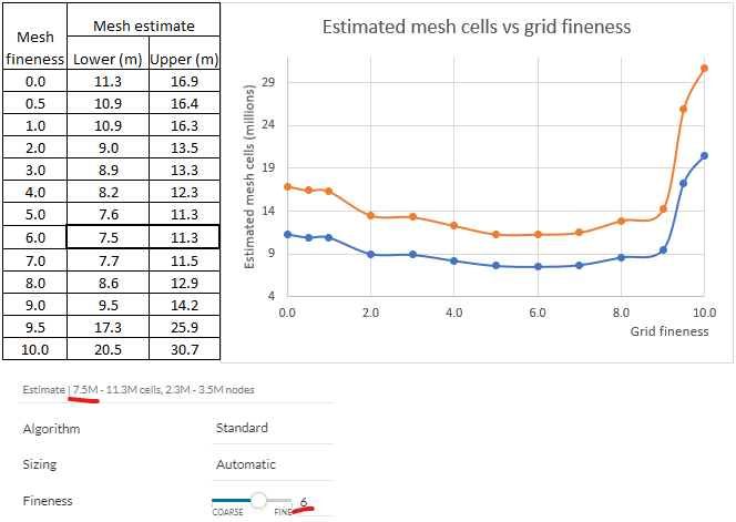
Ok, I undertook some initial testing on cell refinement associated with the overall mesh region and plotted the overall mesh upper & lower cell estimate
I now find in another mesh forum answer that the mesher undertakes finer mesh at particular parts of the model if the overall mesh setting is set to low, ie too coarse.
Hi, As soon as I read your post I thought you were doing a study of the moving wall of a rotating propeller but now I see that your propeller is fixed… so I have deleted everything I was going to write to you… So, go directly to @SBlock’s link.
And by the way… Do not use the standard algorithm. The mesh only needs to be fine upstream and downstream of the propeller. For most problems, standard meshing is a waste of elements and CPU time.
Hi Jairogut,
Thanks for thinking about my problem again and the recent feedback on looking at @sblock link and reference to fine mesh up/downstream of the prop. Interesting comment on “standard meshing a waste of elements & CPU time”, I’m always keen to reduce the CPU time so I’ll rethinking how I do this meshing. I’ve done some reading just need to do a bit more. Thank you for your guidance.
Regards Chuck
Hi Sebastian, Just rereading my reply to you, I meant to say “I’m struggling with compressible flows”. Well it seems I need to learn a lot more about meshing, thanks again.
Regards Chuck
It’s a waste for your problem and external aerodynamics. not so for other different setups (for example pipe flow).
But again, you are simulating a propeller with a fixed mesh… it did not appear to me that you are using an actuator disk… what is the point of it if I may ask? Or am I wrong?
Hi Jairo,
I’m using an MRF rotating zone with the propeller and had good Incompressible results and I am now trying to apply a similar sort of setup for Compressible flows.
Recently I’ve had several mesh errors and fails experimenting with Compressible flows and I will need to re-read the Hex-dominate meshing and Compressible inlet/outlet pressure flows etc and start afresh. Whilst I’m a civil engineer I find it difficult to grasp Simscale documentation and need to reread documentation several times and or follow a close example. I know its not a cookie cutter approach to simulations, but I was hoping that someone had covered a large rotating propeller with compressible flows as an example that I could adapt, but I have failed to find something with Hex mesh, rotating object, and compressible simulation. I might go back to basics as you suggested. I keep persisting, but thank you for your time. I’ll get back to you later on after I have done a bit more investigations. Kind regards Chuck
Ohh I understand. I asked because in the case you provided I did not notice the MRF rotating zone, so therefore I was obliged to ask
I know it may be difficult to learn from the documentation, but let me tell you that SimScale has done a spectacular job (learning from OpenFOAM documentation from scratch is much more difficult). As you may know, Simscale’s CFD module is based on OpenFOAM.
And well, since you have clarified the MRF, for the grid you must learn how to handle the parametric mesher and do the following:
Use a very coarse background grid (for example for a 20 x 20 x 20 x 20 box).
Make refinement boxes, sequentially. The idea is that the upstream and downstream of the propeller are refined for example at level 5 or 6 max.
Make a surface refinement of the propeller and add layers to guarantee a y+ between 30 to 150 if you use wall functions. You should investigate what the y+ is and what size it would be for your operating regime. Ensuring this from the middle to the outside of the blade is very important.
When you do this, we check the level transfer of elements from the surface to the outside.