The height above the roof level where the flow is influence by the cube is 1.5*5=7.5m according to handbook and for SIMSCALE this might look similar (although above this height on sees in the SIMSCALE velocity contours still having a small dip above the end of the cube).
So I am getting slightly confused. I might be ‘mixing’ things (which?) too much? Any help is wanted. Thanks.
So what Turbulence model is best for me? Speeds of the air between 2 and 15m/sec; ABL with z0 around 0.5 to 1m; heights of obstruction objects between 3 and 25m; the distance of the measurement points at around 15m height and minimum distance of 25m (and maximum some 250m) from an obstruction object.
In general, for CFD for wind in the built environment there are several guidelines. The cost action 732, and several other guidelines (richtlijn wind antwerpen; city of london) suggest to use either:
RNG k-eps realizable k-eps
I’d pick the latter.
SST models usually give a poor representation for built up environment, esp. near the ground.
That said, the wake close by the building may be better captured by SST, but usually you are looking at wakes further away, thus use realizable k-eps.
Bert Blocken also did great research on this subject (as did many others). Also for validating CFD to measurements in the field (campus TUe).
that said, also think of the surface roughness of the approach flow, or the flow will speed up unnaturally before it arrives near the object (ABL homogenieity). And best to set the inflow boundary condition to the “lid” as well, or you’ll lose turbulent energy near the top.
Thanks for this input!!!
I will try this realizable k-eps in my next run!
Thanks for mentioning Bert: we plan to look at some academic link for our traditional windmill project (see if w actually can measure wind around a windmill and then also simulate it. Thus given use comparison opportunities.
At this moment I am using a roughness height of the ground of around 20times the Z_0 (of the ABL = 0.5m): using Custom boundary. I found it interesting (strange) that the higher roughness height I use (I tried 0, 0.5 and 10m ); the higher the velocity becomes (at the same height). I had expected a lower velocity, but that might be because I am new to this discipline!
Where do I put the ‘lid’ on the Velocity Inlet boundary of SIMSCALE. I have now ABL formulas for the velocity, k and eph,
I have now run the CAD model with realized k-epsilon turbulence, the difference for my situation is not that much
I am still using 10m as roughness height for the ground (Custom boundary). I still did not yet found out what ‘lid’ means for the Inlet boundary. Hope you can direct me? Thanks.
Where can I increase the elements per edge? Is it in Mesh and then Fineness (which I have on 5)? So I need to increase this to 10 (also the maximum). Correct?
I will remove the top surface from the ‘Wall 3’ boundary and include it in the ‘Velocity Inlet 1’
I tried to increase the Finness to max (10) and includse lid of ‘External Flow Volume’ to the Velocity Inlet 1.
That did not work: Got an error message that had keywords like ’ the size of the objects’, ‘in relation to the finness’ (I forgot to cut&paste that error message:-().
So I brought it back (to Finness=5) and kept the ‘lid’. Now SIMSCALE tells me:
"The model contains faceted geometry. When Advanced concepts are used, the meshing pre-processing requires some boolean operations to be performed. The support for facet geometry is limited in this case.* This mesh meets our quality criteria."
So there is something with faceted geometry (don’t know how to improve that), but at the end it tells that the mesh meets their quality criteria, so I assume the mesh is all ok…
I added in the Velocity inlet 1 (So I did no define a new Velocity Inlet, hope that is ok?) also the lid of the ‘External Flow Volume’. And now I got an error in the running (at 12%): “Gauge pressure field started diverging. Please check the mesh quality near the reported location and try refining the mesh. If the problem occured near a boundary, please check the boundary conditions. In case of doubt, please ask for assistance via our support chat. Gauge pressure = 1.06176e+15 at position: (159.5 m, 91.33 m, 0.3265 m).”
At the mentioned location I see a simple box object. So have no clue about this, did not happen when the lid of the ‘External Flow Volume’ was a Wall.
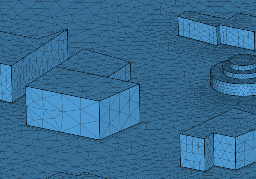
This image shows that there are only 2 elements over the height of some of the houses, that should be more. Usually you’d want to do that by setting the size explicitly, not use a simscale specific slider.
Then:
the height of the total domain should be higher. that cost 732 paper I mentioned gives some better insights. (try 4x higher)
the roughness on the bottom should be set according to the help of simscale (constant = 1)
boundary layers should be added to the bottom. Simscale fails to do that automatically.
the mesh has a poor non-orthogonality, increase the correctors for that. (and / or improve the mesh)
(- and use the pot-flow initialisation, is faster)
overall, I would not use the default simscale meshing, it is not good. Fill in manual sizes for all you mesh work.
Hope this helps. I’ll not look into the forum again, so hope that this was helpful.
Otherwise, it is wise to do some of the general tutorials of simscale.
Think this is indeed not correct what I had. I used a flow region height of 40m (2.5H) and my object of interest was H=16m high. So now I changed the flow region height to 100m (6H).
I used 10m, more or less 20times the z0. By the way I see this also a (lower) recommendation for terrain scale 6 by SIMSCALE: a factor of 10.
I don’t understand this point: I set the roughness height in the boundary ‘Custom’. Anyway I use a boundary layer for all surfaces of the flow region. Perhaps I misunderstand this point?
If I look in the Mesh quality file I see: nonOrthogonality Acceptable range: 0 to 88 min: 0 max: 89.96142835721949 average: 15.115932162422554 standard deviation 11.87045328471216 median: 14.786002566388524 99.9-th percentile: 56.65718636249987 99.99-th percentile: 67.50480604953317 99.999-th percentile: 77.50601308919153
So this looks all ok, correct? By the way what is: ‘pot-flow initialisation’?
At this moment I used the default meshing, the manual of Fineness setting did not work for me (all setting above 7.5 and 10 cause same issues). It looks the the Roughness height of ground is a reason for terminated Runs. A Roughness height of 1m works mostly, but a 3, 5 or 10m Roughness height causes Gauge pressure field started diverging (see another mail thread: Gauge pressure field started diverging - #9 by jjansman ).
Hi, one last reply,
-domain height
most mesh elements are near the bottom / around details. In the top of the domain there are usually few elements (bigger). For that reason, it does not hurt to have a slightly too high domain. A too low domain affects the flow near the ground, and thus is a problem.
roughness value
I’d use a factor 10 with Cs of 1. so for 1m y0, that is 10m z, Cs 1.
Boundary layers
usually, but default simscale sets BL’s. For custom boundaries it does not, therefore these need to be set manually in the mesh. All non-slip boundaries need Boundary layers.
non-ortho
maximum non-ortho of 89.96 is high. The rest of the elements are fine, so you might be able to stick to 2 instead of higher.
For the “potential flow initialisation”, this usually improves the convergence a lot. (also correctly pick initial values for k and eps). Also increasing the relaxation factor (esp. k / eps) can help in that case.
meshing
a default mesh is no good. looking at the mesh of the run incomp. 7 of that shared project. THe mesh near the top of the domain is too fine (too many elements), no boundary layers on the ground surface. and too coarse near the buildings itself. Where possible, pick values (eg 1m elements) instead of names (eg. medium fine).
Extra tip, test the meshing in a very small version of the model. Just a few houses. this helps to check how to set things up. takes a minimal amount of time and costs. This holds for everything, test small. goes quicker, and saves money.
Thanks for being patient here. I was confusing boundary conditions and boundary layers! I had set the Custom → boundary condition. But I had not set the Mesh → Refinements → Inflate boundary layers. After adding that (the default values), I don’t see the error Gauge pressure field started diverging anymore. So that helped.
I had indeed high values of most Mesh items (ratios, non ortho, etc) when using my stacked cylinder trees. Sometimes a vertical line was include in a cylinder by the mesher(?) and that caused very small areas (large ratios).
I now used in CAD mode Simplity → Cylinder, and that removed these large values. A tree as a cylinder is ok-ish perhaps. But I tried in a earlier very smaller model a ellipsoid-tree, but that caused already Mesh problems, so I stopped using that.
But I want to have a better tree model(then a cylinder), so back to the ellipsoid solid: But very basic meshing problems happen, as the error happens very early in the meshing calculations: The meshing failed on the following entities: face 2@Solid 66.
Everytime I do a re-mesh a different solid is mentioned…
I will make a new topic in this forum about this.
I still need to work on this. That basic solids (a stacked cylinder and a ellipsoid) case problems concerns me. I must lack knowledge still on this.
I did that, tested different trees, etc. in a smaller models first. But at the end my Community Plan(s) does not really look at pricing. And I have relatively a lot of time;-). But I fully understand your point.
Thanks again for your help and I will keep experimenting in this virtual wind tunnel/CDF.
I used 10m, more or less 20times the z0. By the way I see this also a (lower) recommendation for terrain scale 6 by SIMSCALE: [!!!THIS LINK IS NO LONGER AVAILABLE!!!]: a factor of 10.