Collaborative simulation project? Multiphase flow around a boat hull

@quequen
Thank you for the data! I did some quick calculations. The Waterline Length l_{WL} of the boat is 6.7 \text{m}. Based on the relationship between hull-speed u_{hull} and l_{WL}:
$$ u_{hull} = 1.4393\sqrt{l_{WL}}=3.73\text{m/s}$$
So I think I’ve underestimated the speed! The Froude number can be computed as
$$ Fr=\frac{u_{hull}}{\sqrt{g_0 l_{WL}}}= 0.46$$
According to [references] (http://www.prirodopolis.hr/daily_phy/pdf/speed.pdf), the wake angle \theta_w for boats travelling at hull-speed is usually 19.5 degrees. Assuming we’re interested in a wake region that is approximately 10 times the l_{WL}, I’ve modified the domain size to include the entire potential wake region. I’ll now run a simulation with the right speed and geometry bounds, and will update with results soon!

Thank you once again for the observations. This is exactly why forum discussions are so productive. :smile:

Based on @quequen’s suggestions, I modified the domain size and supplied the correct input velocity. I ran a short 3 second simulation just to see how the wake starts developing, and it already looks much better than last time.

Waiting now for a 20-seconds run to finish.

2 Likes

Wow! now the transverse wave system is cool, showing his typical curvature. Diverging system still don’t appear.
Check depth, shallow waters (assuming non-adiabatic walls of the domain) should have a strong effect on wake, even making the transverse system disappear. But even then, the divergent system should be there (Edit: but not in the same way! ).
Distance between crests now concur with Fn=0.46 (slightly longer than LWL). Although Fn=0.46 is pretty high for the kind of hull you are analyzing. If the hull has not vertical freedom, it will lead to error because the amplitude of the wave under the hull will make the yacht “lighter” (less water displacement than really needed). There is a way to simulate this in a more realistic way: sink the hull slightly at the beginning of simulation so that, when at Fn=0.46 , the water volume displaced by the hull still equalls yacht’s weight.
About Kelvin wedge, some concepts can be considered beforehand:
Divergent system is always there, no matter the yacht velocity, hull shape or water depth, (Edit: but it can widen a lot in shallow waters!) .
Transverse system appears at low Fn up to, say, 0.6 At higher Fn the hull may be planing and then it dissapears completely.
Transverse system can dissapear in shallow waters even at low Fn.
The tangent angle inside the divergent system isn’t constant: It goes smaller when Fn goes higher.
Longitude of transverse waves is proportional to yacht velocity only.
Amplitude of transverse waves is proportional to yacht velocity and yacht displacement, and may be affected by hull shape.

Typical Kelvin wedge behind a ferry, traveling at about Fn=0.3 or 4.9 m/s (taken from Google Earth)
LWL: 26.5m
Distance between transverse waves: 19m

8 second Simulation visualization. As per @quequen’s observation, for Fr=0.46, both diverging and transverse wave systems appear in the beginning but then are lost - probably because the domain is still too small.

Now running a simulation with domain four times as big.

Hi @sjoshi it’s great someone continues this thread!

As @quequen seems to be a bit deeper and up-to-date with the topic of hull’s design – I had the lectures and some practice years back now :slight_smile: – I’d still like to add something from me.

I’ll focus on your last outcomes as I assume these are the best one so far. So I took your animation, cut the very last frame and this is what I’ve got:

(Sorry if I missed it in text.) Roughly measuring the distance behind the hull is about ten times the length of a yacht. The width is more than five time the hull’s width – I like it. But what I don’t like and don’t understand is why there is such a small gap between domain inlet and yacht’s bow? Look at the picture above (and your earlier picture, orange one too). Didn’t you notice that? (Sometimes it happens that we miss obvious things :slight_smile: )

I assume the water table is expected to be flat (no waves), but here we can see clearly some wave is forming in front of a bow. – The same phenomenon you can observe in your previous simulation (!) - I would say you should move the object further down the domain and I would keep the other dimensions as they are. It’s nice to read your discussion about wake shape, but don’t forget about what’s happening in front. BTW residuals go smooth and stable with it?

Also: the time step here seems to be 0.1 [s] (animation contains of 81 frames). It’s fine. But with domain size at 30 [m] and velocity 3.73 [m/s] the time of 8 [s] you set hardly covers (or even doesn’t) the time that a particle of water needs to travel from the inlet to the outlet. If you start your simulation with zero velocity it’s not enough.

You have written you had quadrupled the domain size. Personally I think it’s not the right way. Not at this point. First I’d like to get rid of that wave at the inlet, obtain smooth and undisturbed inflow and only then move my attention to the wake.

So please, if you could run this simulation in approximately the same domain, but move the object about two hull lengths back. You have the precise values, but I’d like to ask for domain and object placement like this:

And, if you start with zero velocity, I’d like to see results after at least 16, maybe even 18 seconds minimum.

Big PLUS for you for running this simulation with full hull, without symmetry.

Finally, could you paste in velocity and pressure fields at symmetry plane? @quequen mentioned something about shallow water and draught, so I’d like to see if there is any influence of domain bottom at it.

Sorry for the hiatus! There were multiple things in the simulation definition that needed correction. I will summarize them here:

Domain: The aim of this simulation was to capture the Kelvin pattern of a boat. As described in depth by @quequen, this required a certain constraint on the size of the domain (19 degrees spread on each side). Also, as @Maciek rightly pointed out, the boat needed to be places at a distance from the inlet. Finally, the bounding box was altered to keep a distance of approximately 2 boat-lengths to the front and sides, and 4 boat-lengths behind the geometry.

Mesh: There were two main issues with the mesh. The first was about the refinement at the water level not being fine enough to capture the waves. That was corrected by setting a base mesh of discretization of 0.5\text{m} in x, y, and z directions - on top of this, the boat was refined to level 4, and the water surface to level 3. Region of refinement of the water surface was about 0.5\text{m} above and below the water.

The second issue with the mesh was the generation of waves at the inlet in the solution. This was being caused as follows:

  • For this simulation, the inlet was split into air inlet and water inlet. The boundary between these faces was located at -0.4\text{m} in the z direction.
  • However, during meshing, the interface was moved a little since it naturally could not be aligned exactly at that distance. It was a little higher than -0.4\text{m} (-0.375\text{m}, to be precise).
  • When initializing the water phase, I was using a domain-based initialization method, and the height of my cartesian box was exactly at -0.4\text{m}. This was causing the inlet to be a little higher than the initialized domain, and caused the formation of waves at the inlet.

  • After realizing this issue, I modified the cartesian box height to -0.375\text{m}, and the problem was solved.

Solver settings: The solver being used was the LTS (Local Time-Stepping) Multi-Phase solver. In essence, the “time step is manipulated for each individual cell in the mesh, making it as high as possible to enable the simulation to reach steady-state quickly”. It took a while to get the combination working, but eventually stable runs were possible. I ran simulations using two time-steps: 0.005\text{s} and 0.0005\text{s}. Runtime was 20\text{s}.

Steady State for 0.005\text{s}:

Steady State for 0.0005\text{s}:

Clearly, 0.005\text{s} timesteps failed to capture the nuances of the Kelvin pattern of the boat’s wake, while the 0.0005\text{s} timesteps were fine enough to take into account the sensitive wake phenomena.

The following animation shows the solution approaching steady-state with time:

The project will be in a share-ready state by Monday. Thank you for all the help, @quequen, @Maciek! :smile:

3 Likes

Awesome, congrats @sjoshi looks really nice! Do you have the total X force ? Does it converge at the end of the run?
I still don’t understand if the boat is freely floating and triming in your simulation, or is in a fixed position at a certain Z value?

@quequen

I still don’t understand if the boat is freely floating and triming in your simulation, or is in a fixed position at a certain Z value?

Thanks, I forgot to mention this fact: the boat is fixed in space. As you recommended, the water level is assigned such that it submerges the boat upto the point of inflection at the bow.

Do you have the total X force ? Does it converge at the end of the run?

Here are drag, lift and variable convergence plots:

Drag:

Lift:

Convergence:

Even though the variables seem to converge in the convergence plots, the drag and lift seem to create a pattern that repeats itself over time. Could this be due to the fact that the boat is fixed in space?

Also, as @Maciek requested, here are the pressure and velocity slices at the center-plane:


2 Likes

Hi @sjoshi,

Your results for drag and lift do not look right. I would expect parameters to ramp up to a steady state value.

I’m not familiar with fluid simulation but this problem looks analogous to a solids simulation where the friction penalty coefficient or penetration penalty coefficient is too high. This causes instability over time (in the case of friction, slip and grip or in the case of penetration, bounce). The results look just like this i.e. the solution converges at each time step but the forces are not stable over time. Also, the instability tends to overestimate the forces. The solution in a solids simulation is to keep reducing the magnitude of the penalty coefficient until the solution becomes stable.

The fact that the solution has converged just means that the internal and external forces are balanced at each time step. If the forces oscillate over time the solver simply finds a solution to balance the oscillating forces.

Many years ago I did some testing to measure boat drag. We towed the measured vessel with another vessel using a tow line with a load cell. I remember that the drag force was consistent over time, for a given speed.

As a rough guide you may be able to estimate the drag force with Dave Gerr’s formula.

Assuming:
LWL = 22 ft (water line length)
v = 3.9 kts (velocity)
m = 7000 lb (displacement, just a guess)

The speed length ratio is:
SLR = v/(LWL)^0.5
SLR = 3.9 / (22)^0.5
SLR = 0.831

The required shaft horse power is:
SHP = m /((2.3 - SLR)*8.11)^3
SHP = 7000 /((2.3 - 0.831)*8.11)^3
SHP = 4.14 hp (3080W)

Assuming a propeller efficiency of 55% the drag power is
P_drag = SHP * 0.55
P_drag = 3080 * 0.55
P_drag = 1694 W

Therefore the drag force at 2 m/s is:
F_drag = P_drag / v
F_drag = 1694 / 2
F_drag = 847 N

MODEL POSITIONING
O, now positioning looks much better to me.

Also @quequen let’s don’t push it too much at this stage :slight_smile: Personally I prefer step by step approach. To me it was obvious from the very beginning the model is firmly set in its position. I get your point in terms of tilt (heel?), draught etc. but let’s solve one thing at the time.

Adding tilt is not a problem with cut-cell mesh. Releasing some degrees of freedom may be problematic. In longer term however, yes – definitely. But now, I’d like to see full convergence and full control of the free surface.

INLET CUT
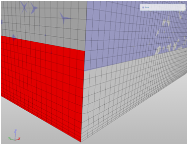
You know what @sjoshi? I also experienced this strange issue at the inlet you had. But in my case I created my domain in CAD program, then cut the inlet surface into two surfaces so that I could later on define them as air and water inlets and only then exported and meshed.

Mesh was generated with no problems. Even mesh division fits to surface division.

(gray – model | red - water inlet surface | light blue – air volume)

Obviously both the surface cut and air/water volume division are at the same height.

I don’t know if it has any significant influence on simulation’s run, but to the record:
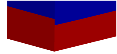
step zero

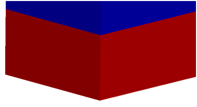
final step (for this particular simulation)

SIMULATION TIME STEP
Previously, based on your animation, I’ve assumed your step was 0.1 [s]. Now, I tested it and see that it was around 0.005 [s]. - It’s just a small clarification.

MODEL
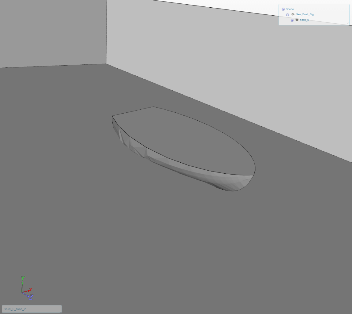
Is it a surface model? In that case, now I understand why @quequen was so keen on z-direction degree of freedom. Why did you decide to run it like this? Any particular reason?

Make your life easier and close it :wink:

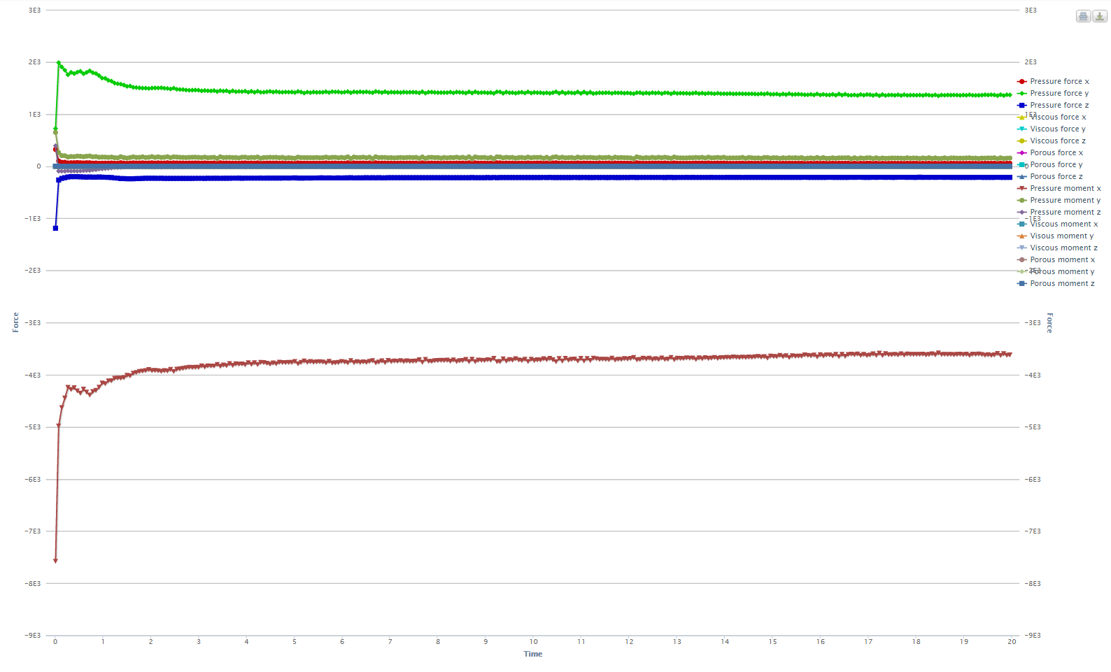
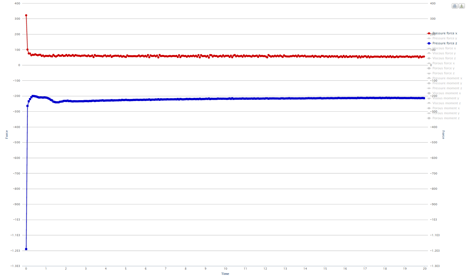
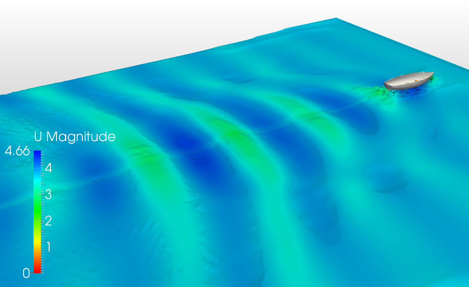
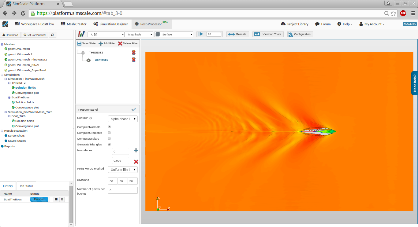
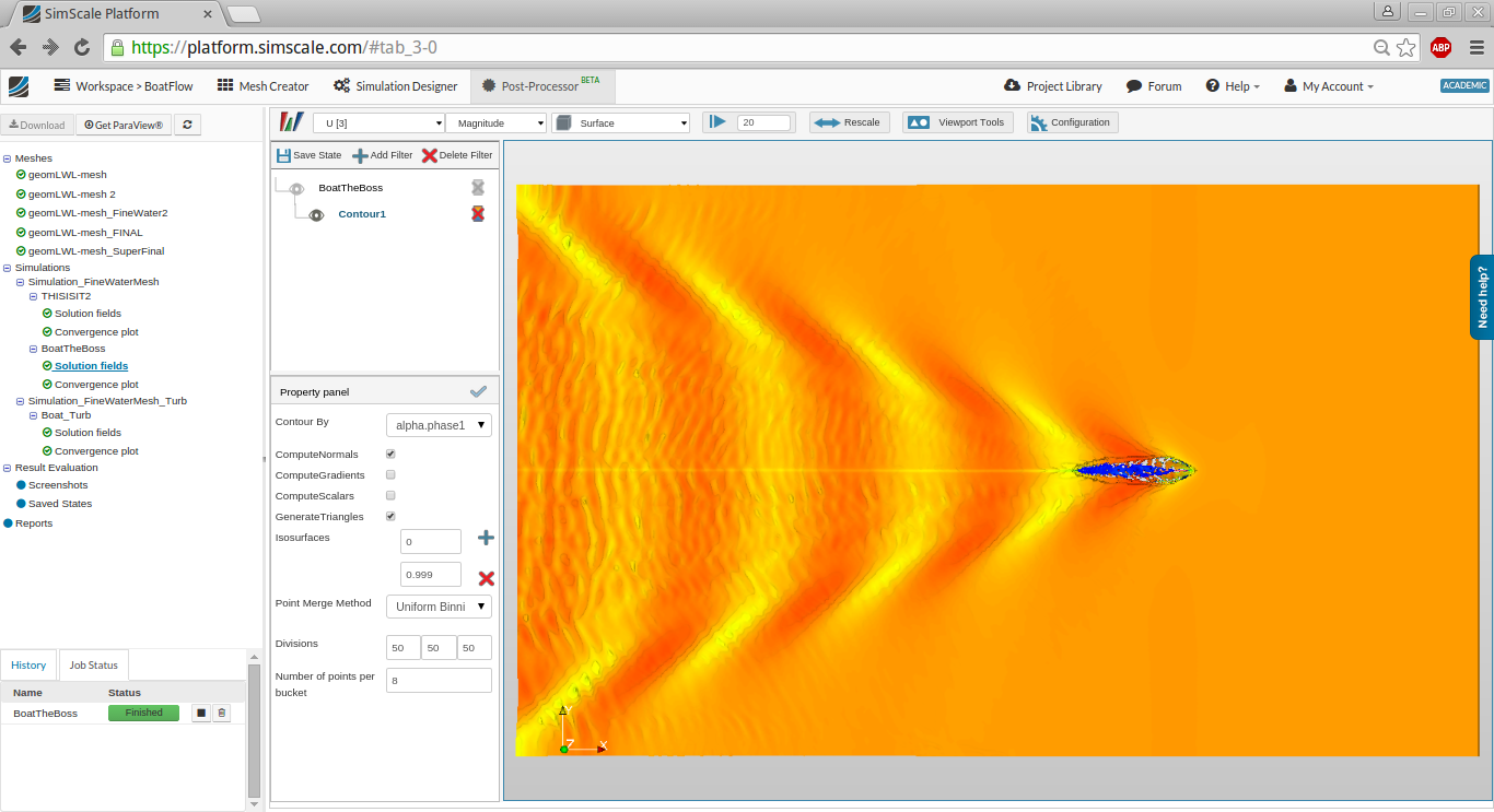
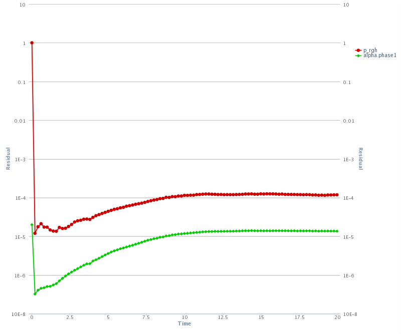
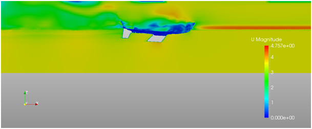
Looking at free surface and velocity field it’s difficult to believe that pressure and phase ratio converged so well.

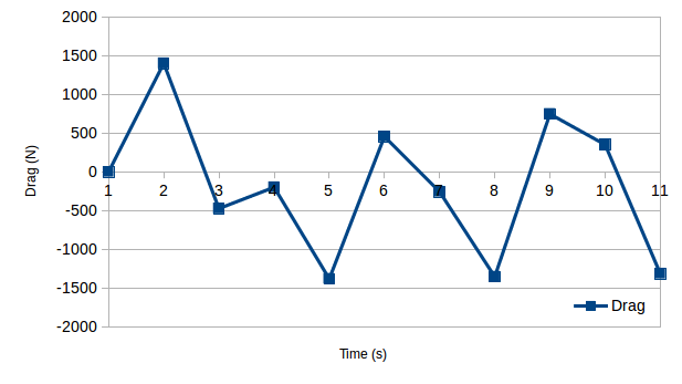
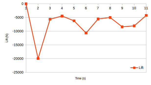
I agree with @BenLewis - forces at your hull look random.

In terms of formulas: I’ll try to find some time and look for it. If I succeed then I’ll ask you for some more details.

RESULTS PRESENTATION
I’d like to add a few words about results presentation – in general.

  • Remember that you see much more than me, @quequen or anybody else, so try to present your material bearing this in mind. For instance: when I presented results of my ROV simulations my main aim was to give basic information about simulation and show correlation rate between experimental and CFD data. I added colourful pictures just to make the topic more vivid, more attractive and eye catching.

Now, when you add your pictures - in my opinion - you can get rid of all that unnecessary elements from it: interface, frames, blank spaces etc. It will make your pictures clearer.

  • Please, for the same case, try to keep to constant ranges if possible (velocity mostly, because it’s something you can control :slight_smile: ).

  • I really like that reversed colour pattern when you present waves coloured with velocity, but…

  • …I’d like to ask you for one more thing here. When you show us waves, plain (not discrete) palette of colours is very good approach. We see smooth velocity changes – super. But when you show cut planes with velocity or pressure fields than it’s not a good idea - at least not always.

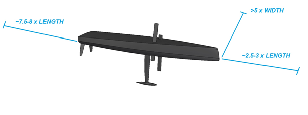
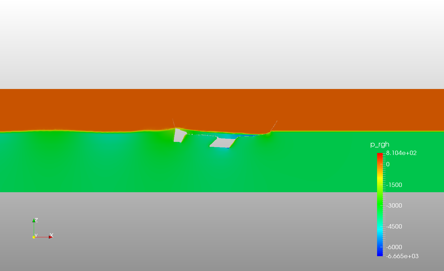
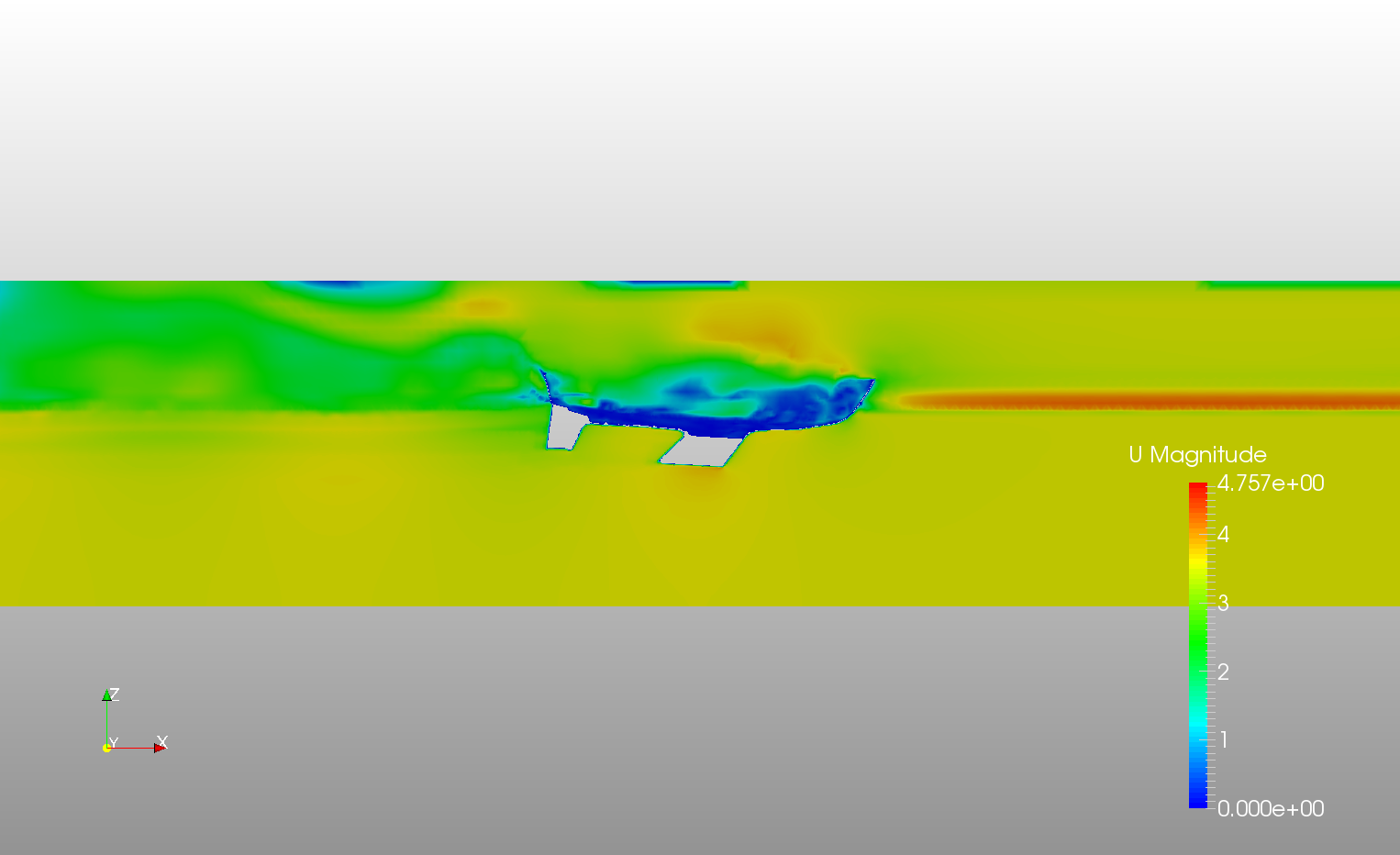
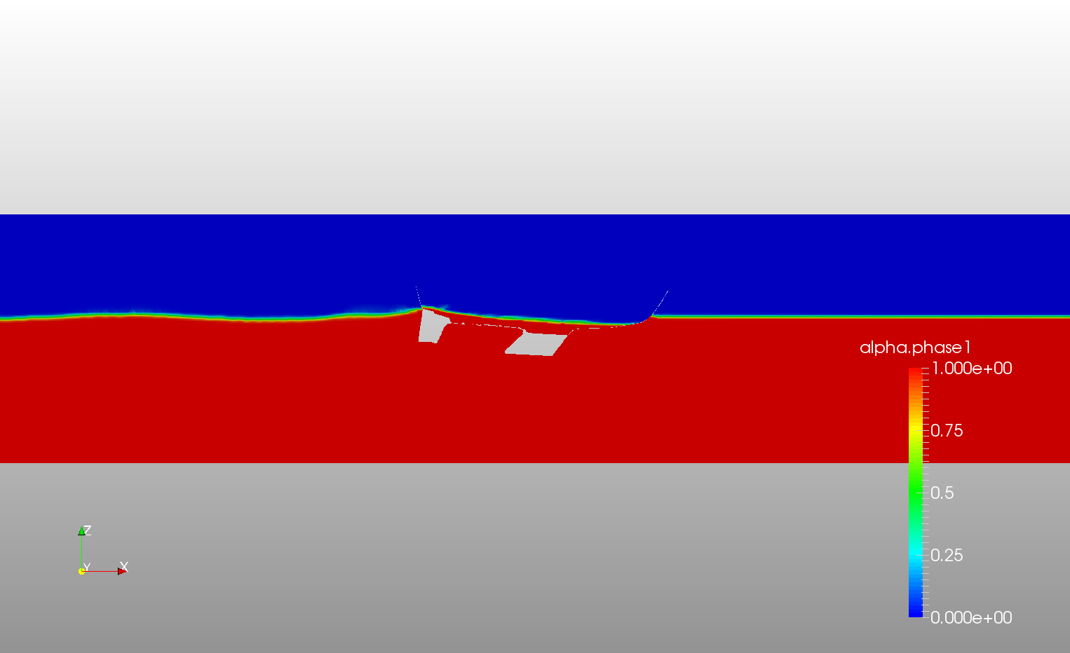
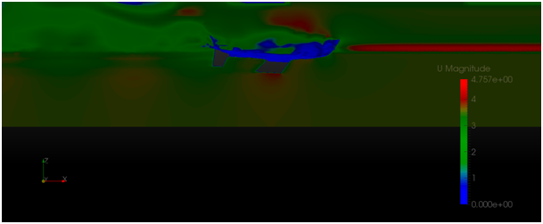
I asked you for cuts as I wanted to check the domain vertical size. From what you presented it looks the domain is both too low and too shallow. In terms of the surface model I’ve already mentioned above and I’ll wait for your reply. Here, however, I’d like to show what the problem is - in my opinion.

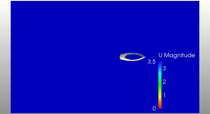
Below is your picture in two versions (I cut unnecessary blank part at the top and kept the one at the bottom to keep the scale bar):


As we can see in the first picture there’s a lot going on in the upper part. I omit boat interior, but there is something at the inlet too (green band in the right top corner). Also just above the water table air velocity is worryingly high – I assume the velocity fields are bonded and homogenous (both have the same value).

I wear glasses but still can see some barely visible colour patches below the hull. So I took photoshop (free photoshop online) and played a bit. After a minute or two I got this. It seems there is a significant interference of domain’s bottom.

Naturally if you’re familiar with your problem, ran a lot of simulations than you have a feeling and you know where you can turn the blind eye. But here, I think the domain should be higher and deeper.

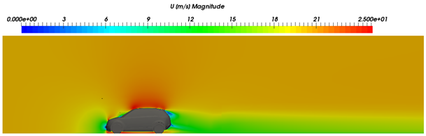
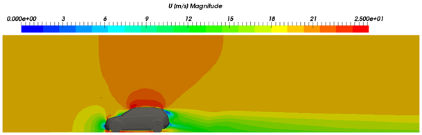
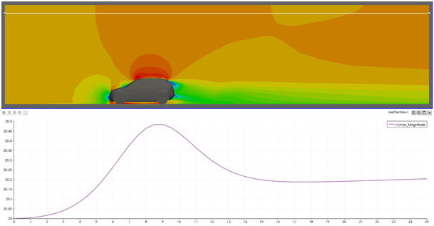
Maybe some example from my compressible test runs:
wide colour range palette

discreet palette

discreet palette with slightly different range plus velocity plot along the line

As you can see the domain seems to be high enough. But when you go deeper you discover that it should be a bit higher and maybe even longer.

Of course here delta is about 2.5% and probably I can ignore it, but still… That’s why they often have such ridiculously big domains.

Let me know what your thoughts are.

2 Likes

Hi @sjoshi, as @BenLewis stayed, there’s a problem with forces. Total X force (Drag) should become steady after a few seconds. Fixed Z position of the hull shouldn’t be a problem for your velocity and Rn. If something as a Karman Vortex is raising behind the hull, it is not visible in your graphics.
By the way, @Maciek, I personally prefer complete screen captures because in that way part of the interface and settings are visible. I have a lot to learn before using the interface properly :grimacing:
At this stage it is premature to compare with existing and real data, but reaching that point there are many well known studies out there. Perhaps one of the most famous is the Delft Series (DSYHS), Delft University recently published all the data, including hull shapes used on tank testing for over 30 years of studies.

This document may be of interest: An extensive cfd analysis (using ANSYS CFX) of one of the Delft hulls.

@BenLewis, @Maciek, @quequen

The force plots indeed look quite suspicious - thank you for bringing it to notice.

I will dive in and look where the issue could be and update here.

@Maciek The visualization tactics of scaling the the important range of data values indeed do help convey a clearer message - I shall keep that in mind.

Finally I had time to catch up on this thread! Impressive work @sjoshi! Looking forward to the next iteration of the simulation results - it looks like you’re getting there. My 2 cents on the simulation:

  • Agreed with @Maciek, that the computational domain needs to be deeper to avoid interaction of the flow field with it (I like the expression “ridiculously big domains” :smile: ). However I doubt that this is the main reason behind the incorrect results.
  • @BenLewis: I think @sjoshi is using a local time-stepping method so numerically it’s possible that transient patterns appear towards the end, looking never really like a “steady state”. However I agree that the question is if what we see is physically correct - the drag and lift plots do look questionable. @gholami mentioned that a good way of assessing the quality of such simulation results is running the same simulation with different time-step length to make sure the results are independent of the time discretization. Probably too early right now but once the results look more trust-worthy
  • What about the mesh around the hull itself? On the image it looks quite coarse. Do the result fields close to the hull look mesh-independent? Could be worth looking into this and adding some refinement layers there.
  • @quequen: Thanks for linking to the Delft Series. Great data! This is definitely something we will look closer at!

As mentioned in the beginning of this thread I have little background in boat hull design. Therefore I am also very interested in learning more about the general approach to these design projects in terms of simulation. @quequen: You asked if the boat can move freely in this simulation. This method is in the product backlog and will be integrated moving forward. But how important is this kind of analysis within the design phase? Comparing it to other design processes and applying the old “Crouch, Walk, Run” principle, I would assume that this is rather something I do at the very end of a project as it’s quite computationally intensive and rely on faster steady-state, fixed-boat analysis for the main part. Would you agree or are the assumptions behind this analysis type too vast?

@dheiny, yes I agree: step by step. Regarding oscilating forces, the document I attached previously throw light in many issues about this kind of simulations. Page 20 and figures 16-17 show how forces oscilate for a while before converging and, as expected, this issue reduces when Fn increases (time-step is 0.02s). At page 28, fig. 23 shows that a fixed geometry throw good outcomes up to Fn=0.4 but higher Fn increases dynamic forces too much, therefore agreement with experiments is lost.

Hello fellow engineers,

The problem with oscillating forces might have something to do with the geometry being bad. Here are a few snapshots showing the old geometry with selection of external and internal faces:

As one can see, there exist surface intersections between external and internal surfaces. I chose a simpler geometry that I closed from the top. Now, the geometry is free from surface intersections:

With this geometry, I re-ran the simulation. Now the forces converge to a constant value. Water flows in the -z direction.

Here are the forces in the important directions, i.e., x, and z directions:

Please note that the actual values of these forces might not be accurate, since on the platform only 1 reference density is used for computing forces on the selected surfaces.

The Kelvin Wake remains the same:

3 Likes

Very neat @sjoshi! @quequen and others: I think it’s worth putting together a webinar/tutorial for such kind of simulations to enable new users faster. I think especially the phase fraction concept / initialization of water/air makes this approach a bit tricky in the beginning. What is your preferred way of learning such new methods/softwares? Would be great to get some opinions on this - check out this post: How to best learn simulation?

1 Like

@sjoshi, it looks great! Some details may still remain but I think you have a strog start point for this kind of simulations. @dheiny I agree, this simulation deserves some webinar/tutorials (perhaps 2 or 3, 15 minutes each?), including voice comments on how to perform the settings, particularly the phases issue. My choice is webinars or tutorials, and a good printed manual (that’s why I asked for a .pdf manual, instead of online manuals). Please remember that my geomety is still there if you want to play with it. I would now try some leeway angle (angle of attack), may be 3 or 4 degrees, bow to port, to catch appendages behavior and a more realistic X force.

@quequen,

regarding how to learn simulation best, we’re in the middle of collecting more feedback and a little survey to steer the type of learning material we want to provide in the near future. I added your opinion there as well!

I wanted now to follow @sjoshi’s work on the boat flow and set up one myself. Did you already upload your model to a SimScale project? If not could, you do it and share the project with me? We could see how far we come before asking @sjoshi for help ;).

Best,

David