I’m testing three different noses but with one of them the simulation stops at 0.1% and I can’t find why. I literally copy-pasted the other simulations that ran just fine. The simulation that gives me problems is “Muso 0” of this project
Hi @wilove!
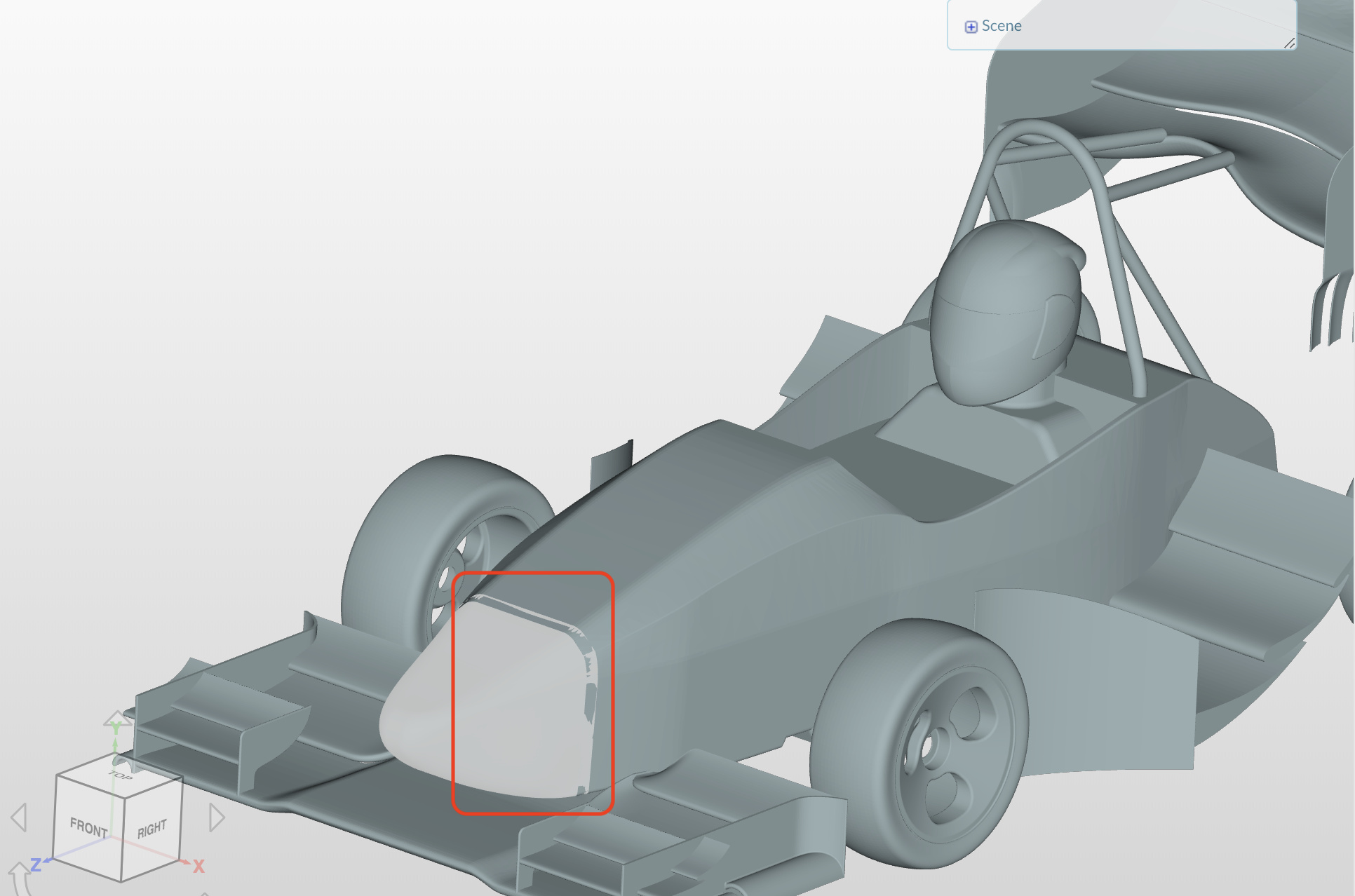
The surfaces of your vehicle are not split and the surfaces overlap as well. You have to meticulously make sure that your geometry is well defined otherwise you are going to have a bad time.
For any other suggestions my colleagues and PowerUsers @Get_Barried, @yosukegb4 and @pfernandez might help you out here.
Best,
Jousef
I’ve tried various adjustment but the simulation is still usuccesful.
- I modified the geometry to avoid surfaces overlap
- I removed the rear wing and the middle wings (i’m interested only in the nose) in order to improve the quality of the mesh.
- Verified that there were not any open spaces in the geometry
I really don’t know what to do.
Hi @wilove!
Please give us some time to investigate this issue - might take some time but we will let you know if we fixed it.
P.S.: Can you please split the surfaces and see if that helps? 
Best,
Jousef
Oh, I’ve uploaded the wrong geometry for the latest try, I’m really sorry! Now the geometries that are uploaded are correct.
P.S: before the latest try the surfaces were splitted (and the simulations didn’t run anyway)
Jani (@jhorv_th) and Yosuke (@yosukegb4),
can you help out @wilove by splitting the surfaces properly in order to get the meshing done ? That would be more than great, thanks a ton!
Best,
Jousef
Hi there,
I’ve been having a look at the project, just a visual inspection of the mesh tells us that there is something wrong.
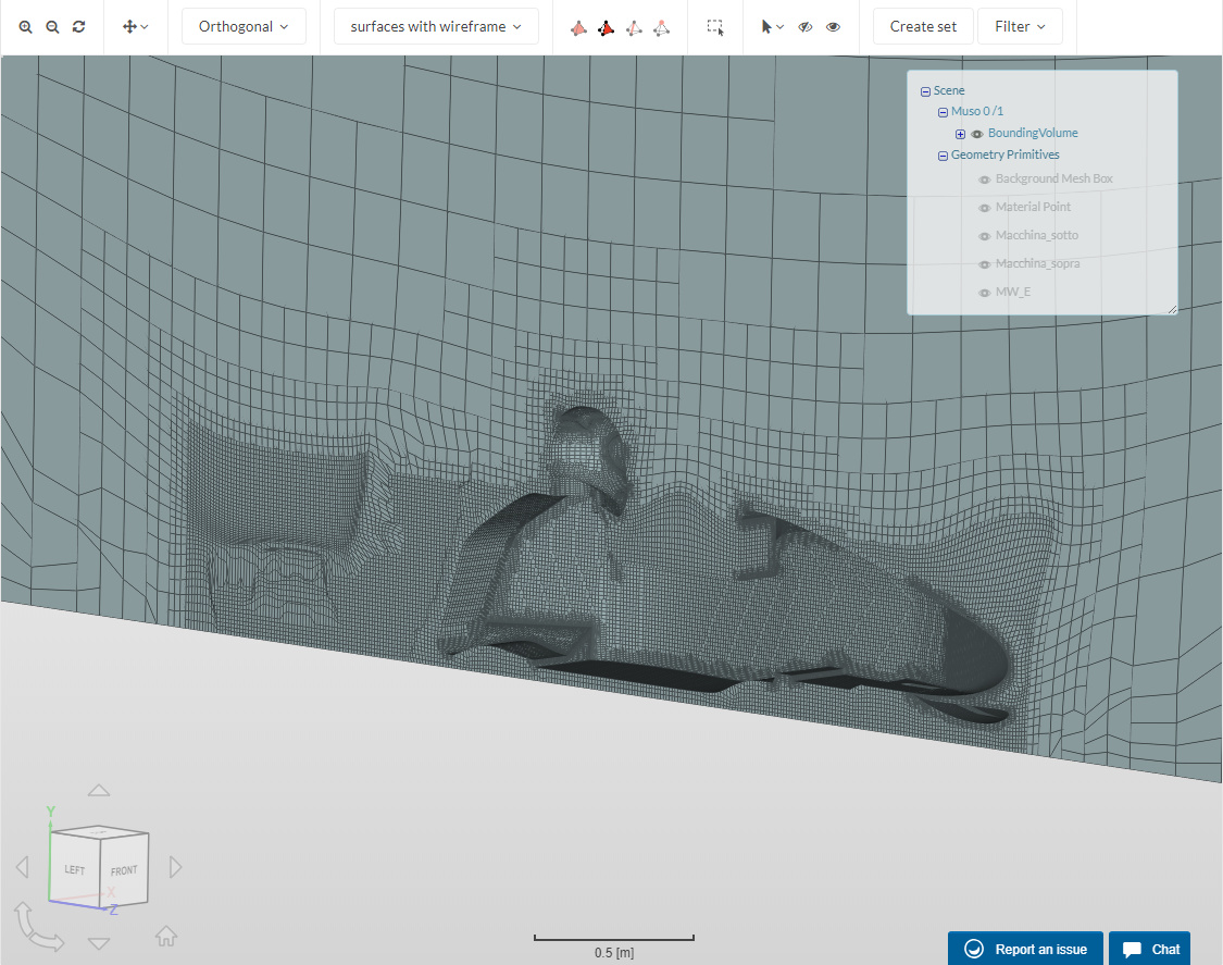
You can see that mesh quality is sub-optimal and it also looks like no prism cell have been created around the body.
Also, if we check the mesh log, we get this:
Checking faces in error :
    non-orthogonality > 70  degrees                        : 11231
    faces with face pyramid volume < 1e-13                 : 521
    faces with concavity > 80  degrees                     : 538
    faces with skewness > 4   (internal) or 20  (boundary) : 1
    faces with interpolation weights (0..1)  < 0.02        : 67
    faces with volume ratio of neighbour cells < 0.01      : 31
    faces with face twist < 0.01                           : 1317
    faces on cells with determinant < 0.001                : 59
Finished meshing with 13765 illegal faces (concave, zero area or negative cell pyramid volume)
Finished meshing in = 126.53 s.
End
Finalising parallel run
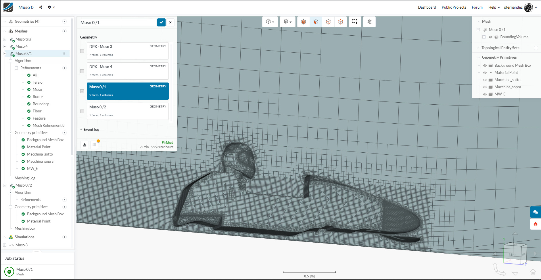
Both Muso 0 meshes look like that. So I would focus my efforts on checking the mesh settings.
Cheers,
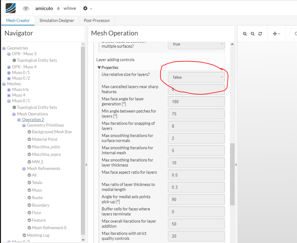
If you enable the relative size option of the boundary layer you should be able to fix your issues:
Checking faces in error :
    non-orthogonality > 70  degrees                        : 0
    faces with face pyramid volume < 1e-13                 : 0
    faces with concavity > 80  degrees                     : 0
    faces with skewness > 4   (internal) or 20  (boundary) : 0
    faces with interpolation weights (0..1)  < 0.02        : 0
    faces with volume ratio of neighbour cells < 0.01      : 0
    faces with face twist < 0.01                           : 0
    faces on cells with determinant < 0.001                : 0
Finished meshing without any errors
Finished meshing in = 190.17 s.
End
Hi everyone !
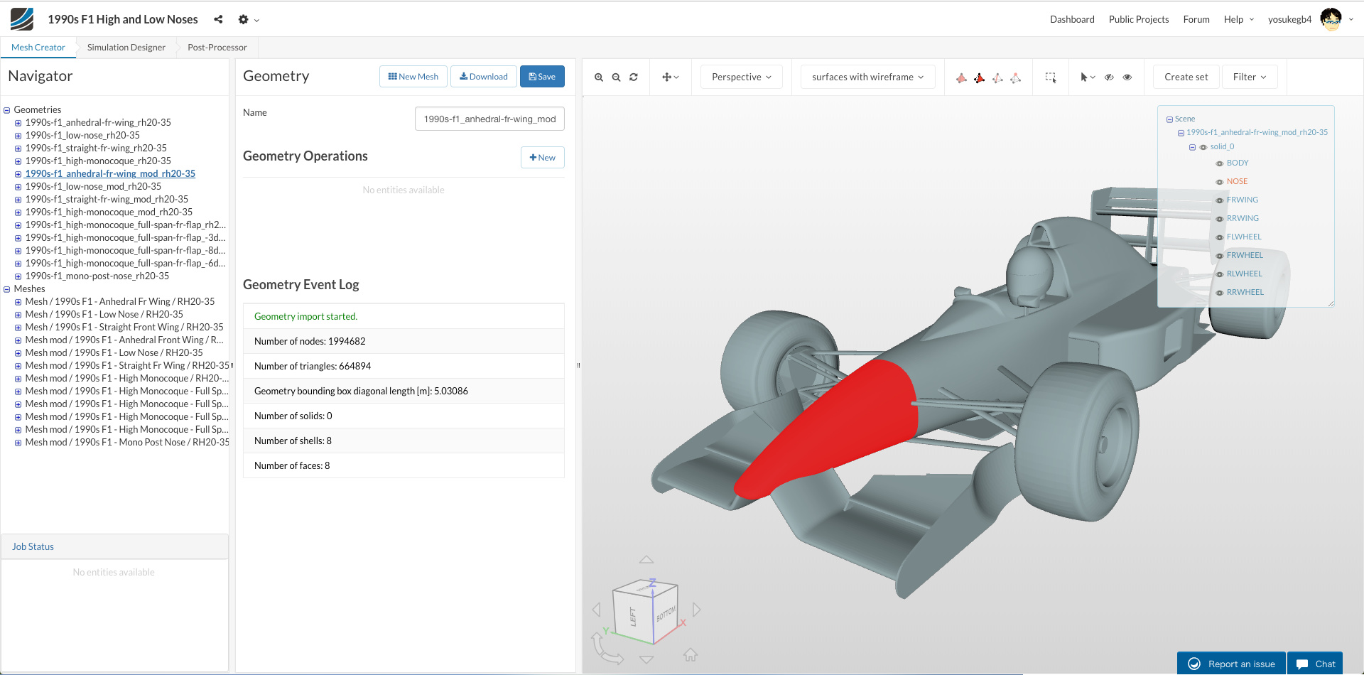
Just for your information, I use a STL file with splitted meshes to analyze coefficients of each part of a car.
I feel it’s more stable to make a CFD mesh from STL meshes than to do it from other CAD data surfaces.
- For example:
- Geometry ‘1990s-f1_anhedral-fr-wing_mod_rh20-35’
in the project of ‘1990s F1 High and Low Noses’ - SimScale Login
- Geometry ‘1990s-f1_anhedral-fr-wing_mod_rh20-35’
I write a way to split surface meshes below.
( I use Rhinoceros for CAD and a mesh editor. )
Best,
Yosuke Yamamoto
1. Convert Surface to Surface Mesh
- Export closed surfaces as a STL mesh and import it to a mesh editor
- OR Convert closed surfaces to a mesh on your CAD
2. Split Surface Mesh
- Split the mesh according to your purpose
- Make sure that the meshes are ‘watertight’ when the whole is one
- If it’s not, edit vertex of mesh until they become watertight
- Make sure that the meshes are ‘watertight’ when the whole is one
3. Export Each Splitted Mesh
- Export the splitted meshes each other as ASCII STL
4. Rename ‘solid’ Names
- Open STL file with a text editor
- Edit ‘solid’ names at beginning and end of the file so that each solid has a unique name
solid NOSE

...

endsolid NOSE
If the names of solids in STL files are the same, it is indistinguishable to select face individually when using it with SimScale.
5. Combine All Surface Meshe STL Files
- Use
catcommand to combine them (Linux/Mac)
cat body.stl nose.stl fr-wing.stl rr-wing.stl fl-wheel.stl fr-wheel.stl rl-wheel.stl rr-wheel.stl > car-combined.stl
6. Upload the Combined STL File to SimScale
- Upload the combined STL file to SimScale
Hi @yosukegb4
Could you explain your use of stable here?
I use Rhino too and have found that I have the best luck with using simply what Rhino classifies as a single ‘closed polysurface’ for my complete Plane or Car geometry.
In Rhino a ‘polysurface’ is made by joining ‘surfaces’ which share at least one mathematically equivalent (to a very high exactness) edge together. A ‘closed polysurface’ indicates watertightness. A surface is a single, untrimmed, mathematically defined entity, not a mesh of many points.
Then I simply drop that .3dm file into SimScale.
In SimScale I am able to multiselect one or more of the ‘surfaces’ that make up what Rhino has termed to be a ‘closed polysurface’ and assign this multiselection to a ‘topological entity set’ (TES) in the geometry tree. (although I never use this step because Geometry TES’s are not persistent after the SimScale volume meshing step ![]() ). I can use a name of my own choosing for any TES.
). I can use a name of my own choosing for any TES.
After I volume mesh a geometry, I start assigning TES’s to it. I always create at least a volume mesh TES named BB that represents the 6 faces of the Background Mesh Box so I can easily turn it OFF in order to view the geometry surface mesh of the new volume mesh.
I have found that TES’s assigned to volume meshes will be available for all simulation needs, whereas TES’s assigned to CAD geometry are only available during the volume mesh creation stage.
From what I can see, I have accomplished what you do (ensuring watertighness and naming surface/surface groups as TES’s of the CAD geometry) in a much simpler manner and I do not have any accuracy loss by creating an STL surface mesh in Rhino and then having SimScale create its volume mesh from an already inaccurate surface mesh.
Am I missing something?
Dale
Thank you very much! This solved the issue
Hi @DaleKramer
I have tried making volume meshes (snappyHexMesh) from STEP/IGES/Rhinoceros geometry files on SimScale in my projects, but the mesher made wrong meshes like shown below.
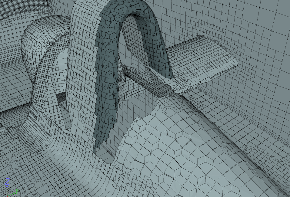
Even for a project other than mine when using CAD files such as STEP data, meshes were not created in the intended shape in some cases like in the issue of the link below.
These problems were solved by using the STL files for geometries.
( I don’t know the mesh creation algorithms well, but I think that some surface meshes like STL are created and used when creating volume meshes. It seems that the surface data of STEP/IGES/Rhinoceros is not directly used when creating volume meshes. Could you someone explain the right thing about the algorithm of creating meshes, please? )
Anyway, when STEP/IGES/Rhinoceros CAD files are used for geometry data, sometimes there are some surface processes that I can not control (or just I do not know settings for) the surface accuracy.
But the accuracy of STL meshes can be controlled when exporting from Rhinoceros and It can be reflected in volume meshing creation well.
These are just only my narrow experiences, but these are why I feel “stable” using STL.
Regards,
Yosuke
Yosuke,
It looks like I may have been fortunate so far and that you have provided a good roadmap to use if I ever have problems
The SolidWorks CAD file of the topic you linked does not import into Rhino5.
I would not mind taking a look at any misbehaving Rhino .3dm file if anyone has one left.
Dale