Hi all,
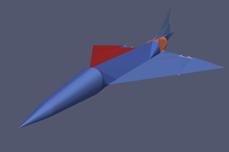
I was curious about some of the Concorde’s delta wing vortex lift characteristics and decided to model it.
I got a great cad file off grab cad and proceeded to de-feature it. It took a lot of de-featuring but eventually sim scale reads nothing too faulty on geometry import other than a vertex warning which I get with most of my projects. The issue came during meshing, it appears that hex mesh is ignoring some faces of my model, namely the faces of the fuselage, and replaces them with several flat planes. The geometry appears correctly in the viewer and the wire frame doesn’t show any internal bodies (there shouldn’t be since I used de-feature to remove internal bodies several times).
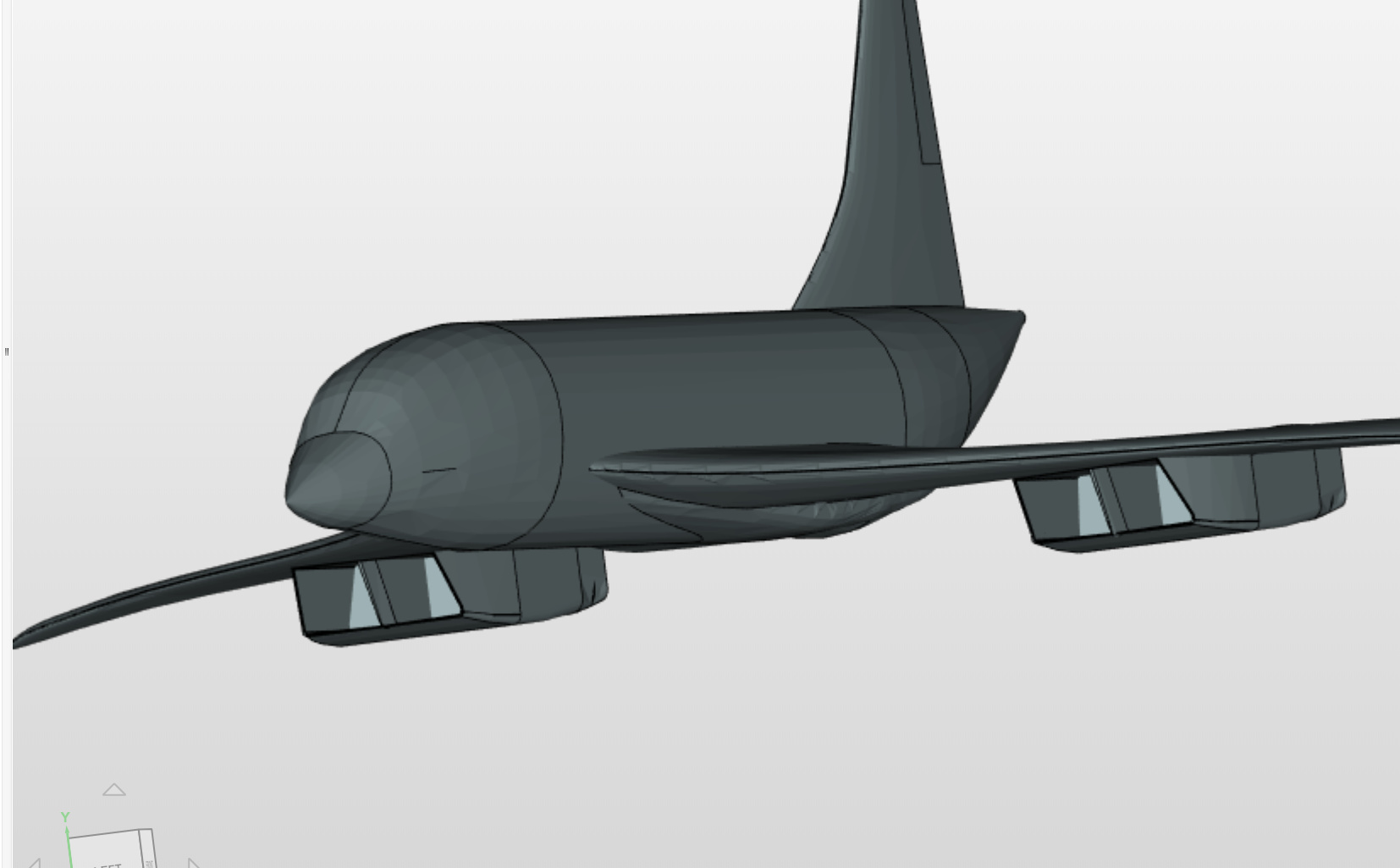
This is a mesh created using a parametric hex mesh wish feature, surface, region and boundary layer refinements.
Fuselage, nose, and tail faces are missing.
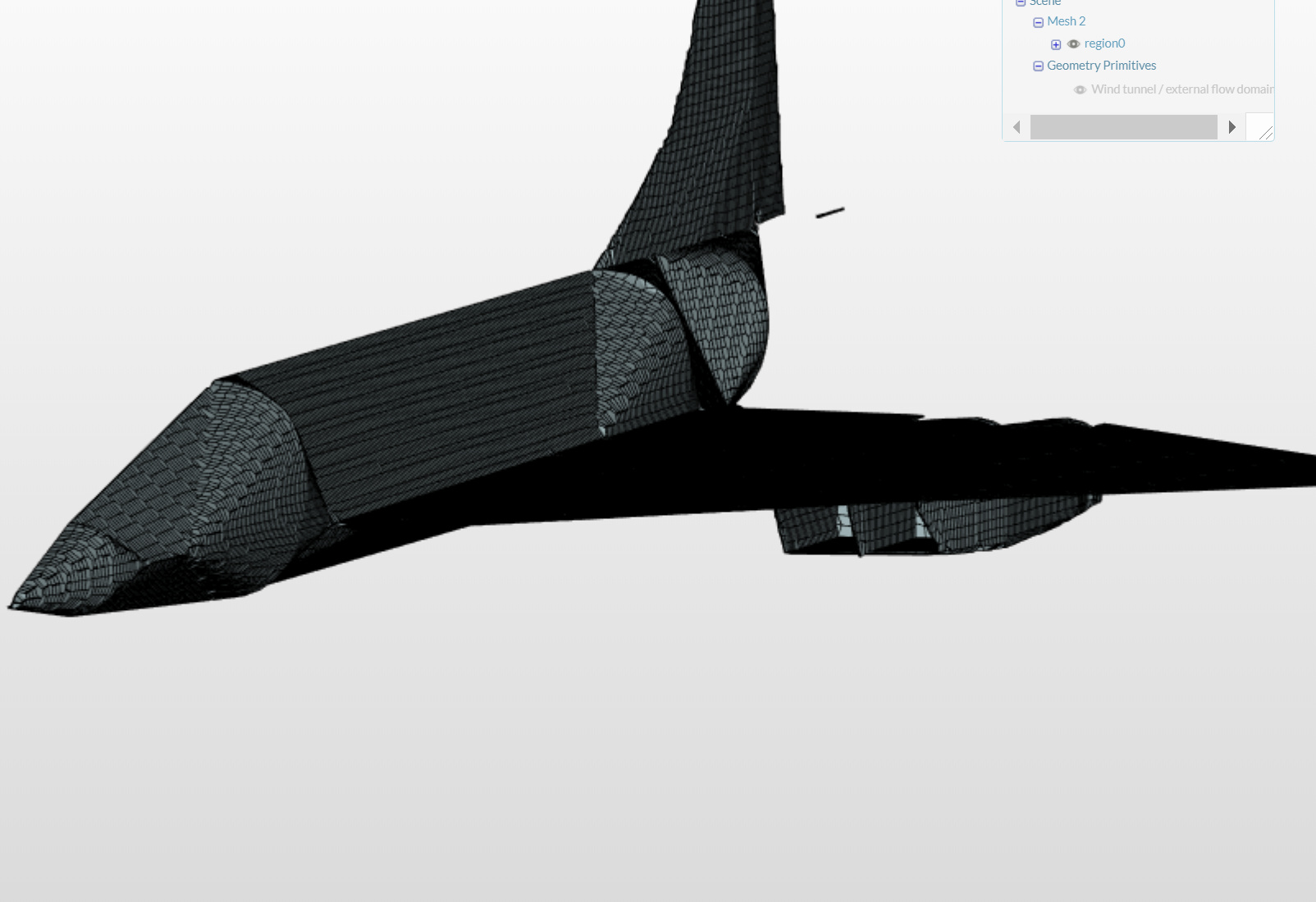
This is a mesh created using the wind tunnel snappy hex mesher to confirm the error.
If it is of any help, I was also encountering a “machine out of memory” on 32 cores error when doing a mesh that, once I got it working (counter-intuitively by decreasing the used cores to 16) was only ~2 million cells.
I’ve moved the material point, bounding box, and changed all the mesh refinements trying the fix this but no luck. I’ve also checked everything the the geometry I can in solidworks and it says all faces are ok.
If any one has any idea how to fix this that would be excellent, it seems like quite the odd issue.
The CAD model looks great! Would be highly interested to see how your project progresses.
So I suspect the mesher is just reading the CAD file wrongly in a sense. I will try to mesh the geometry on my end to see if I can get it working. May I also have the CAD file? I’ll try uploading it in a different format, see if that works.
If you have the choice, STEP is the preferred one since it’s superior in terms of the conversion process to IGES. The STL format can only be used for fluid mechanics analysis since only certain meshing algorithms on SimScale support it.
More information can be found at out documentation: CAD Preperation. Let us know if you have any further question!
Thank you @jousefm ! By any chance have you came across anyone having this “mesher ignoring faces problem” before?
It just seems like the strangest issue to me.
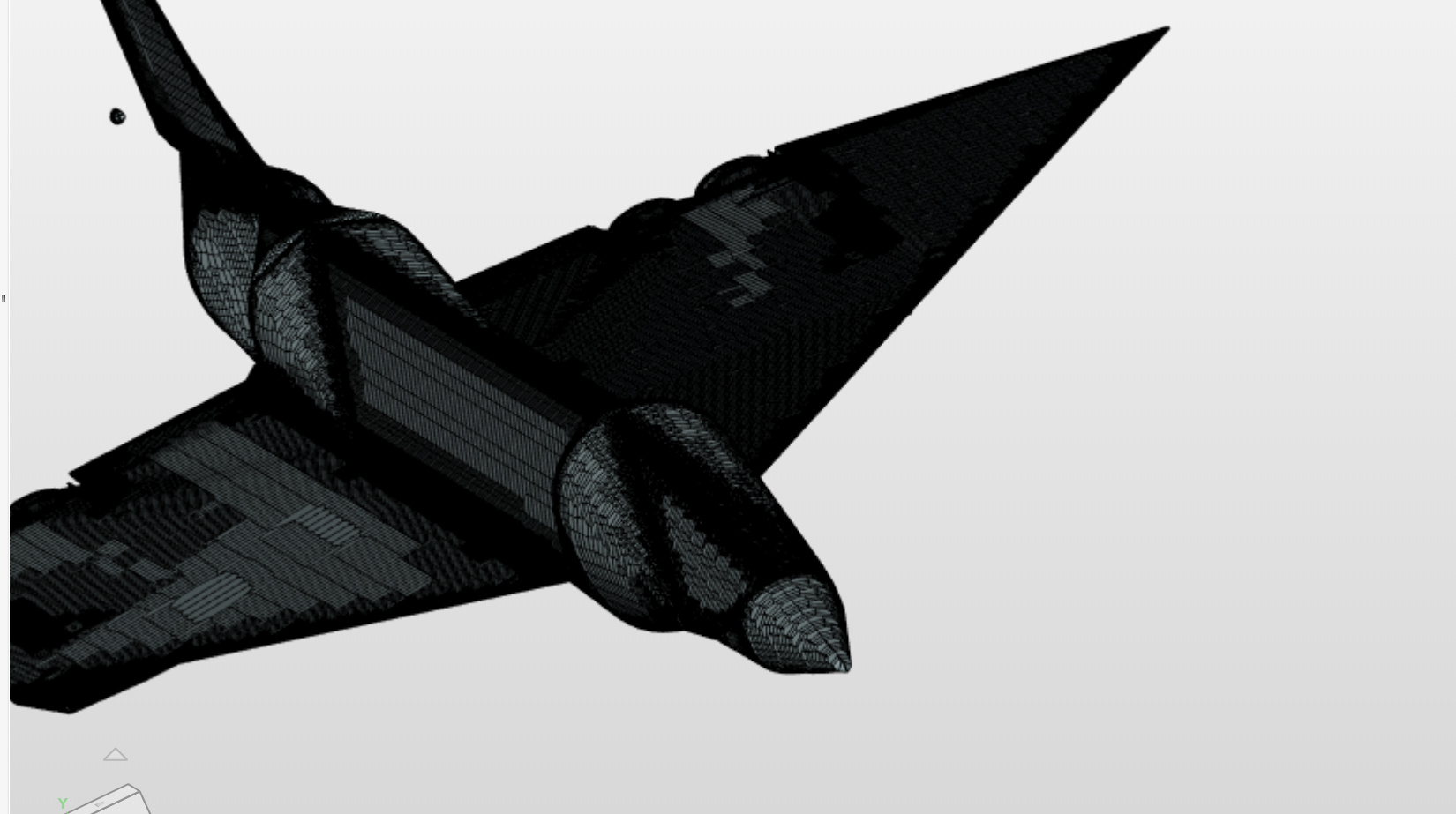
So I tried to mesh the geometry several times but it always cuts off the end of your CAD model as you also have seen in your case, weird artefact. I will try some other meshes.
@jousefm for some reason when I re-uploaded the geometry as an step snappyhex detected the cockpit area of the fuselage but not the rest, not sure why the cockpit started the detect, I’ll try to play around with it more though.
Interesting. I did modify your geometry to IGES and still the same result. I suppose you have tried to upload the entire geometry as STEP. Did you do anything in particular to the geometry that partially resolved this issue?
@Get_Barried the only thing I changed was a face on the engine pod. I don’t think that contributed to the face detection though , again only the very font face detected, still missing most of the body.
I also had a quick look at the model. As you already stated there is a problem recognizing some faces correctly. This seems to happen when the model gets tessellated for the hex-dominant mesher (see screenshot of the stl geometry that is used in the mesher in paraview below)
@afischer thank you for taking a look! If it helps pinpoint the problem I think that there is another missing face, the top of the wing, it’s subtle but the wing generated by the mesher is both substantially thinner and much more of a right angle triangle than the curved wing of the Concorde.
Thanks for the help so far everyone! if there’s any more details I can provide please let me know!
In my experience, this meshing problem occurs when converting a strongly curved surfece (like cylinder) to STL mesh.
On the other hand, CAD files like STP and IGES did not work well on SimScale CFD meshing for my projects.
So I use STL files for CFD meshing that exported from CAD with adjusting parameters.
I often adjust the parameters as below when this kind of problem occurs.
Maximum edge length : smaller
Maximum distance, edge to surface : smaller
( I use Rhinoceros for surface modeling, and I do not know how they provided in your CAD (solidworks?), Sorry. )
If the STL file does not improve even if adjusting the export parameters,
I divide those surfaces on my CAD so that the influences of the of surface curves will be less.
This may not be the ideal answer because it is not a method to solve it on SimScale alone.

 , again only the very font face detected, still missing most of the body.