Keep running into newb problems, I’d really like to speed up the process. If someone is interested and familiar with CFD, please contact me.
Hi @wmcmahon!
I would suggest that you post your problem here along with a detailed description including pictures and the project link (make sure that it is public - if you do not want to then simply share it). We will help you out!
Best,
Jousef
Jousefm,
That’s awesome! I’m brand new and really wasn’t sure if people would help or not.
I’ve tried several variations of this,( https://www.simscale.com/workbench/?pid=1208320352585465688&mi=spec%3A2c2629ed-1a29-442d-a373-17850150d07d%2Cservice%3ASIMULATION%2Cstrategy%3A2).
I’ve burned up nearly a 10th of my community hours and don’t have not achieved anything. Was getting pretty frustrated. Any help or insight would be appreciated.
*edit: “please let me know if my project isn’t accessible from the link above”
-Bill
Hi Bill!
No worries - that’s why we have the forum  Can you give us a little bit more information on the case with some illustrations if possible? What is this application used for and do you want to validate some data on it or perform topology optimizations according to flow behavior? Looking forward to hear from you.
All the best.
Jousef
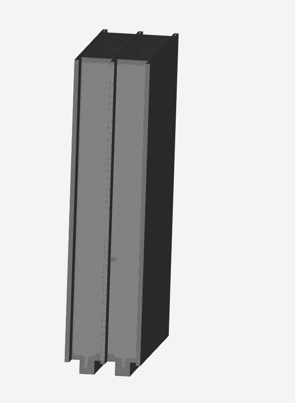
This is used to etch plates, it is important that the flow past the plates is of a balanced volume. The flow direction is from the two slots in the bottom where the plates nest. The plates are held vertically, with the water solution running over the top and into a collection basin. There is actually a chamber that resides beneath the two slots that produces steady pressure, but I removed it from the model because at this point I didn’t want to introduce any additional hindrances to solving getting the simulation to solve without error of some kind.
What do you all think of my boundary conditions? I’ve tried it with walls (internally) specified, with out. With boundary boxes, without. I’m just really out of ideas at this point. Its been alot of time an little return.
100KPA pressure at the base of the etching cell. Solution is free flowing out of the top.
I would model the rest of the catch basin and the manifold that the water is plumbed into below, but I just want to keep things simple to start.
This is all one single solid. I really didn’t see anything that would be too different from the sample CFD (the pipe) that loads with the intro to the problem. I tried to run this using the same parameters. I did get hung up on the “wall” boundary. Also, when I selected the inlet and the outlet on the pipe, it seemed to select the cross section of the opening, where as I was selecting the face that the opening was cut into. I tried to select all the internal vertical surfaces as my “wall” boundary, and I tried to run it with no wall boundary selected. Either way it fails before the simulation solves. So any thoughts would be appreciated.
Hi @wmcmahon!
Thanks for the detailed explanation, I am trying to dig a bit deeper into it and let you know what I think. It would be interesting to know if you have experimental data for that case or any other material (papers would be great - I always ask for them ) to grasp the concept a bit better.
I am waiting for your response - will then try it with a standard velocity inlet/pressure outlet setup and see where we can go to. Also I have seen that you just used the incompressible flow solver, would it not be more appropriate to use the multiphase solver and and some type of pool around your object to see the water overspill?
Let me know what you think. Want to make sure that we agree on certain parameters before running a simulation just for the sake of running it.
Cheers,
Jousef
Jousefm,
I really don’t have any papers for you to check out, I hope a lack of scholastic rooting in the project does not disqualify me.
I would be open to your suggestions regarding the multi phase solver, that would show more appropriate detail.
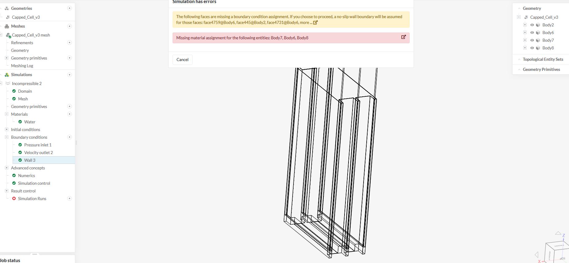
I’m also not able to get past the materials condition errors. For instance, I tried to solve with both ends open. Then I applied thin bodies over the outlet and the inlet (in Cad) so I could select them in SimScale as inlet/outlet boundaries. After the model meshed, the selections were chosen and a simulation was executed, the errors popped up. I went back into cad, applied material properties to the covers and uploaded the revised model back into SimScale. After re-meshing, and following the steps to run a simulation, I’m getting similar errors.
Hi there @wmcmahon!
Absolutely not! It is just a standard procedure to ask which helps in a lot of cases to see which assumptions have been made and if there are plots/data we can validate against.
So regarding your material error I would like to know if you have the intention to give the three plates a specific material behavior and subject them with a temperature load or just keep them as “simple walls”? If it is really just an incompressible flow simulation with an inlet and outlet condition then let me check the geometry first as the internal flow simulation chosen by the automatic mesher deletes the plates from your geometry which is related to your “double-layered” geometry. I usually prefer geometry with one surface because in your setup you have two surfaces per inlet which might cause trouble here. @Get_Barried, any additional input from your side?
Cheers,
Jousef
The three plates are just simple walls. My main question of “how does the water flow between the plates” encompasses other questions such as, how does the water flow out of the exit at the top (is it just rolling over the side, or is it shooting out of the top, which would mean I have to dial it down), How does the water move across the center of the plate (looking down) compared to how it moves near the outer walls. What is happening as it rolls over the top and off the side of the cavity? I’d make changes to find out how much flow is possible before it’s shooting out the top. After that I’d add to a containment box to the outside to find out what I’ll need for an outlet so the containment box is not overwhelmed (and over-flows/over-fills). After that I’d add a manifold box to the bottom and see how this influenced the flow between the plates. Hope this isn’t too much info, but I guess I’m trying to say that I care much more about flow and temperature or mechanical behavior of material is not a concern right now (or probably ever). The geometry I’ve uploaded is just my starting point.
Hi @wmcmahon!
Exactly what I thought of  The thing is that you might need to adapt the geometry as previously mentioned because the plates get deleted during the meshing process no matter where I put the material point. Let me give it some more tries before I confirm that we have to make adaptions.
Cheers,
Jousef
Back with some information @wmcmahon!
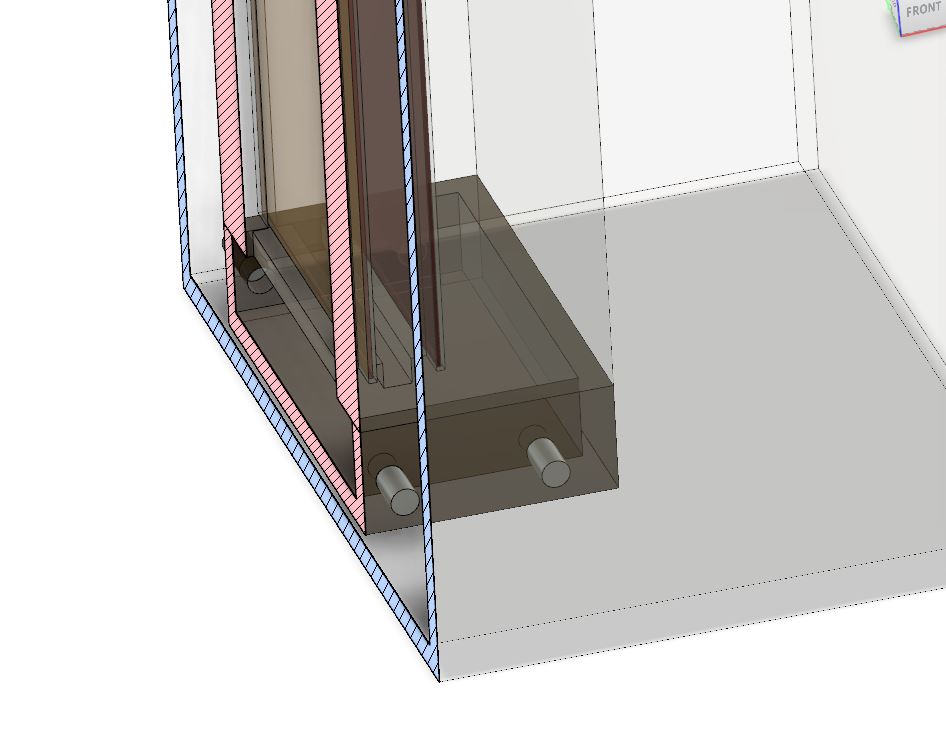
Can you please remove the two face combination of the inlet and make sure everything is created of one layer, makes things way easier. Also the plates will be removed from the mesher in the best case scenario as shown below. Also see the picture I attached that shows that if the material point (indicated by red circle) will be placed inside the domain to make sure that we perform an internal flow simulation, the outside of the domain will be deleted.
\underline{\textbf{Translucent view of geometry}}
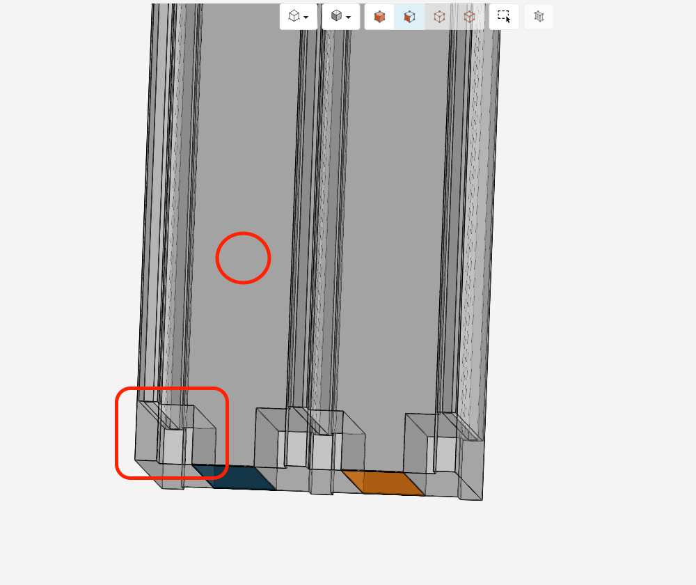
\underline{\textbf{Resulting Mesh}}
The thing now is that you have probably picked the wrong surfaces, no blame because how are you going to decide which of the two surfaces of your two inlets now really acts for the mesh, right? That’s why I am saying that a “single layered geometry” might be a better option here. Pre-processing is everything imho.
Cheers,
Jousef
Hi @wmcmahon,
Don’t be discouraged! CFD is in many ways relatively simple and in other ways, extremely complex. I started it with zero knowledge of anything (not even knowing how to solve PDEs), so don’t worry about the lack of background or the need to have extensive academic background!
Regarding your simulation problems, Jousef has correctly pinpointed out the issue. Pre-processing. In particular, geometry preparation. While he has identified one of the geometry issues, another is the inlet and outlet at the top and bottom of the geometry. Currently, they are being represented by 2 faces. This probably will cause problems during the meshing process. So simply ensure that its just 1 surface for the inlet and 1 for the outlet instead this double laying (that i presume represents some kind of thickness).
Once you’ve solved the geometry problems then we can proceed from there.
Cheers.
Regards,
Barry
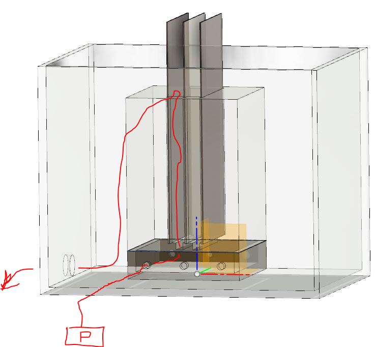
I’m a little confused by this…I need to measure that flow is balanced across both faces of the center plate. This is because the flow into this part is through the two slots at the bottom, originating from a manifold underneath the part I’m trying to work with (originally I had this lower part in my simulation, but I thought I might get the Sim to Solve if I simplified).
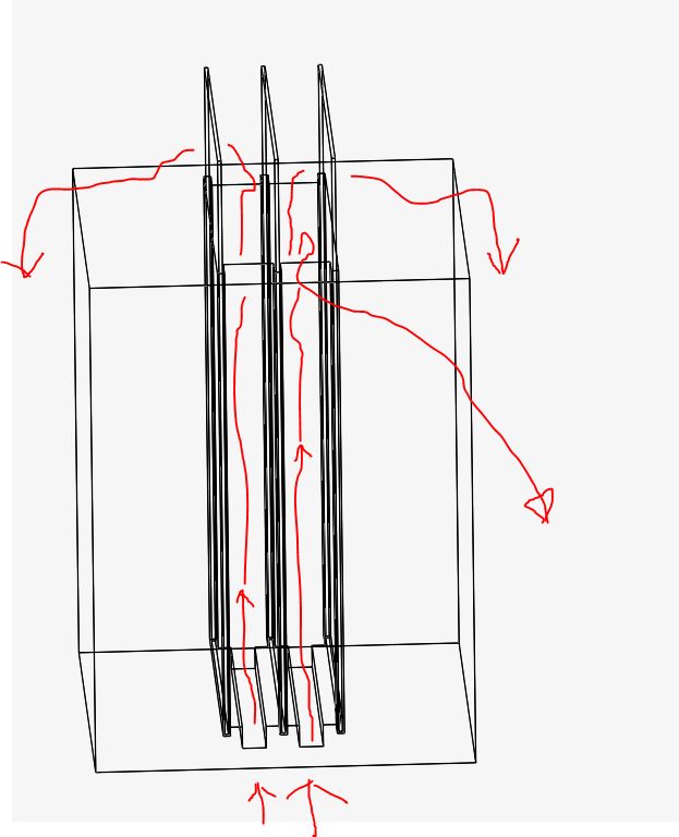
Can I move the material point down into this manifold? I’ve attached two pics, one is a cut-away and one represents an overview of what I ultimately wish to include in the simulation (as described in my prior post). The 6 inlets in real practice would either protrude through the outer container or I would just run hoses to them.
Jousefm,
If I remove the plates from the cell, I’ve not got a simulation of balanced water flow over the center plate through the two slots (that’s what I’m trying to simulate). Can I ask 4 questions?
-
Can I scale it down to solve more quickly and easily (just to start)?
-
Do I need to model everything I want to see (In the simumlation) in one solid (instead of joined components)?
-
Was I correct to place plates on the Inlet and the Outlet for the sake of creating the boundaries? I only did this because my first 10 attempts failed and I was out of ideas to try. I really thought that I was instructed initially to select the face perpendicular (or the face that the opening is cut into) for my Inlet and Outlet points, but again, thought it was worth a try.
-
Where do I select the walls? do I select all of the walls inside where I’m trying to measure flow? Is this even possible?
Sorry to show up and be a pain right out of the gate. I’m just really lost at this and would like to determine if I’m going down the right road.
Hi @wmcmahon!
We are slowly getting there  No worries by the way, that’s why we have the forum! Let me think about the geometry to see how we can take into account all the conditions you want to have fulfilled and make sure that the mesher is not deleting relevant parts. Hope you’re not in a rush
Best,
Jousef
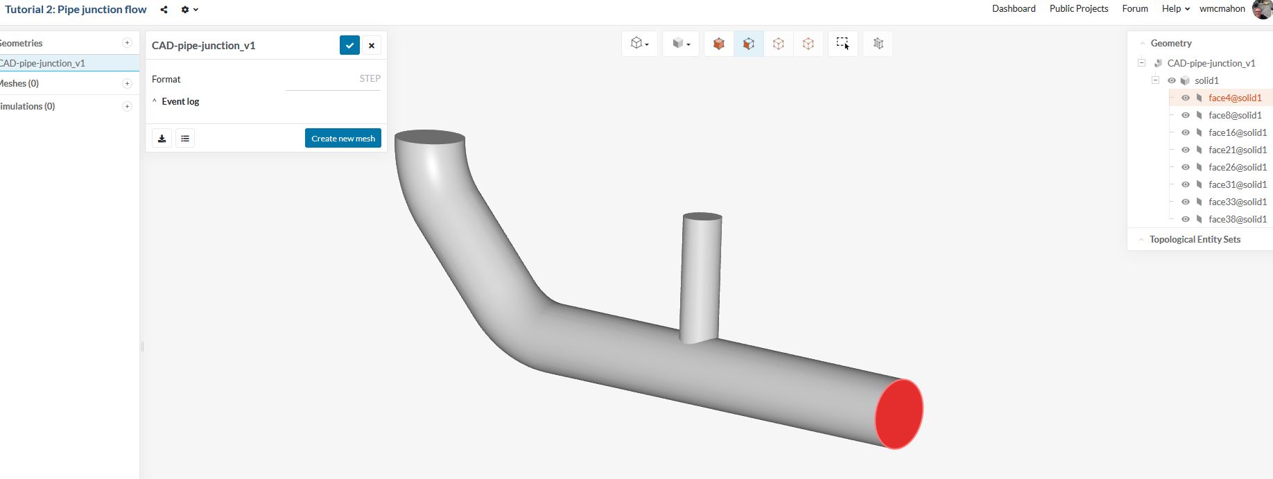
Riddle me this. Can a simulation run (like mine: Metal Etching Cell by wmcmahon | SimScale) with an open end/hole in the model, or does everything have to be covered? I’m asking because I want to know if an inlet or outlet must be a flat plate over the opening, or you can just pick the flat surface that the opening is in. Or am I wrong and it’s something else? What is it? Also, does this run have to have a wall boundary? Why? How do I select it?
Also, What are geometry primitives for?..Sorry for the one sided post thread, but it seems I’m finding questions faster than answers.
What’s the proper volume to pick (for materials)? Do you always just select the whole solid model? How do you not pick the whole model…won’t this assign the volume of water to be the same value as the entire model mass? How can I pick anything different.
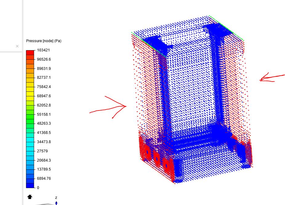
Update: I reconstructed the model from scratch, moved the material point down into the manifold(with the six inlets) and it meshed, but the plates were missing. I ran the simulation anyway and it solved, although it didn’t seem to yield much in the way of useful data. The two surfaces with arrows are the inlet surfaces I chose. It looks like they are both experiencing the water pressure I specified, but it’s not being directed into the inlet holes as I’d intended (as you can see no action on the inside, or the outlet.
I re-executed the mesh using a finer setting, and it said I didn’t have the computing power to solve. So I backed it down the the next coarser setting (moderate) and it meshed without losing the plates. Keeping my fingers crossed that it solves the simulation.!
No dice. With the finer mesh the simulation failed twice with the same simulation (that solved earlier with a coarser mesh). Going to go back into cad, put covers over the inlet and the outlet, re-mesh and see where that gets me. Be back in 12 hours.
Hi @wmcmahon!
The model needs always to be watertight when doing CFD simulations! That means that everything has to be closed. I like however that you modified your model and looks way better and more “CFD friendly” than before. Additionally please remove double layered faces as mentioned beforehand - you still have theses on top (blue faces) as well as all the inlets are still affected. On top of that you set the material point to be in such a way that either the inside will be deleted or the outside box. We will have to figure out a workaround for this - @Get_Barried, can you make a quick suggestion please?
They have several purposes. On one hand you can define them inside the pre-processing step to refine specific regions, you can use them to check if (0,0,0) is where you expect it to be by using a point. Points can be used as probe points to check deflections or other parameters inside your simulation. For multiphase simulations geometry primitives such as a box can be used to define a water reservoir etc.
We usually select the whole domain and assign air to it unless you want to perform a multiphase simulation (which I mentioned earlier). An example can be seen here: Tank Filling Study. In this case you define two phases (0 & 1) and assign them when choosing a boundary condition.
@wmcmahon, please let’s discuss geometry related issues first before running meshes and simulations because they will not deliver what you expect as the mesh is still not what you want it to be. I am currently involved in other projects but will hopefully make some agreements with PowerUser @Get_Barried to quickfix this asap.
All the best,
Jousef
Good Morning Jousefm,
Woke up and the mesh is still solving (7 hours later), it seemed to take so much less time for the same surface area at the same setting yesterday. Does having the window open affect how the mesh runs or the model will solve?
Lets talk about the “double layered faces”. Do you mean faces that overlap (interfere) with one another, or do you mean faces that are on a different cad layer, or are separate bodies/components? The geometry in question has the same material assignment and does not overlap. These are in place so I can select the oulet and inlet boundaries…Like the first surface in the attachment from your tutorial.
At this point I have to ask, do I just misunderstand the entire SimScale paradigm? I.E.: Should I be solid modeling the negative (open) space, rather than the things that I’m going to physically build? Is the pipe in the tutorial a solid model of the negative space or is it a model of tubes (with open space inside) and faces covering the ends. Please Advise!