Hi @wmcmahon,
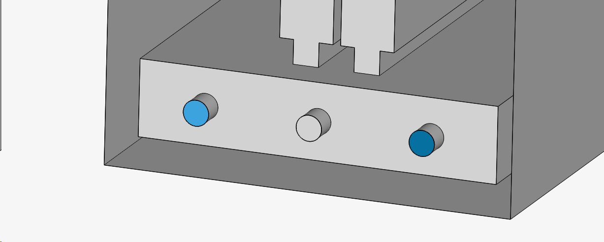
Let me be a little more clear. Referring to your other project, this is an example of what I mean by double layering. In this particular area you have capped the geometry off with a circular insert that is some level of thickness.
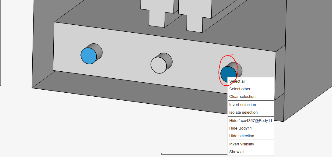
Now I will try to hide one of the circular faces. You can see it shows up as face4357.
After hiding it, it still seems that it is capped, and it is. By right clicking that exact same circular face after hiding first circular face, you can see that it is still capped and shows up as face 4359.
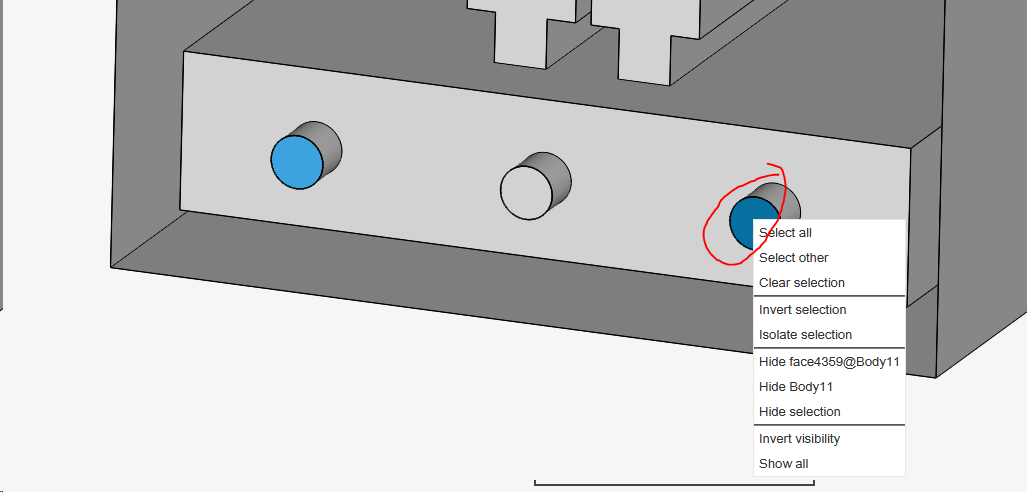
This occurs due to your cap having a thickness, and when insert is read has two caps. You need to ensure that the caps or and inlet/outlet does not have this double face, if not the mesher will not be very happy.
In this case, simply ensuring that the inlet is decided (the holes) and outlet (the top of the box) is sufficient to allow your analysis. Your model must be covered only at the inlets and outlets and are defined by you. I’m not sure whats the best way to explain the overall concept of this that is applicable to all cases, but I think after a few examples you can get the hang of it. Lets work on a case by case basis.
I agree. A model that is not prepared for meshing should never go past the simulation stage. Even if it does, rubbish results are likely to occur.
No, leaving the window open does nothing. Meshing/Simulation is done in the cloud. Leaving the browser open does not make any difference at all. Meshing can take large amounts of time due to poor geometry or incorrect settings. Its hard to tell which part of the geometry is causing meshing issues besides the possible double layering at the inlet outlet as described above. Suggest to start meshing as corase as possible and see how the mesh conforms to deduce where is the issue.
Not sure what you mean by negative (open) space. But in general, prepping the CAD for simulation compared to what you’re actually building is far off and similar at the same time. Bear with me here. You obviously want to keep the CAD you’re analyzing identical to what you’re going to test/build. However, there are things that you need to adjust to prep the CAD for simulation if not you will encounter issues during meshing and simulation as you are probably encountering now. Suppose you put in alot of effort to keep ALL the features in the geometry and prep them for simulation. You may be able to get it running and get good results, but you’re looking at easily months and months of continuous work, which is clearly not a good usage of time. On top of that, keeping those features will only affect your results by a insignificant amount. All that effort is then effectively wasted.
So we will always try to simplify the geometry as much as possible while keeping the most important geometrical aspects that will likely affect the simulation untouched if we can. Regarding the sample simulation, I believe in your terms it is indeed a negative space model. Faces covering the pipe I believe are singular piece and do not have a thickness to avoid that double layering problem.
Hope this helps.
Cheers.
Regards,
Barry