PROJECT DESCRIPTION:
The whole thing is a ventilation pipe with a box attached to it. Inside the box there is an air restrictor that is supposed to re-direct part of the airflow (coming from bottom-up) into the box.
WHAT I HAVE DONE SO FAR:
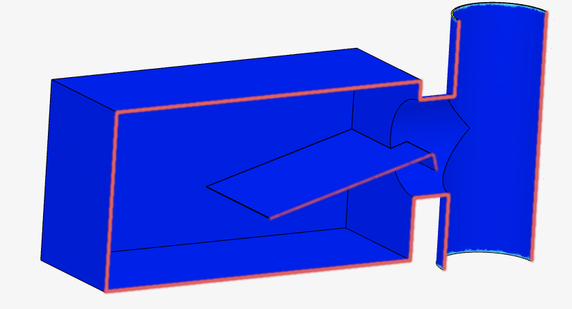
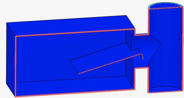
I have 4 models loaded into the document (geometry names given in the brackets):
-
made of surfaces (no solids) and WITHOUT air restrictor (Vent_tube._faces_simple)
-
made of surfaces (not solids) and WITH air restrictor (Vent_tube._faces_with_restrictor)
-
made of solids with air restrictor but WITHOUT any surfaces or solids that form the inlet and outlet ventilation passthrough shapes (Vent_tube.no_in-out_faces)
-
made of solids with air restrictor but WITH solid bodies that form the inlet/outlet ventilation wholes (Vent_tube.in-out_faces_solids)
====================
The simulation works fine only in case 1)
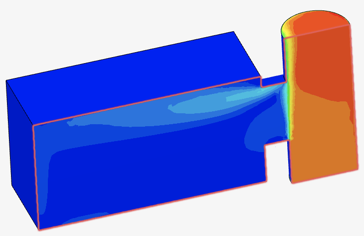
This is an expected and satisfactory result.
In other cases, I wanted to add a restrictor and see how the airflow changes.
====================
In case 2) I get the following errors:
- except for one have an Advanced Concept assigned to them.
- There are settings defined in the simulation setup which have empty assignments and hence will be ignored for the simulation run. Names of the settings that will be ignored: Momentum source 1
====================
In case 3) I chose the edges of the vertical ventilation pipe as shapes for inlet and outlet boundary conditions (bottom one for inlet, upper one for outlet).
The result is that I don’t see any air flow circulation inside my model. Seems like the airflow is going through the walls of my construction, which are supposed to be solid! rather than INSIDE the construction.
====================
In case 4) I chose the solid bodies that form the inlet and outlet shapes of the vertical ventilation pipe.
The result seems to be the same as in case 3)
WHAT DO I WANT TO ACHIEVE:
I would like to make a simulation of the air flow through the model from the bottom inlet to the upper outlet (to see how the air restrictor affects the airflow)
I can’t understand what I am doing wrong.
LINK TO THE PROJECT: