im wondering how i get simscale to work testing my fpv frames stress testing thank you!
Hi,
In case you are new to SimScale, the best place to start is definitely by running the step-by-step tutorials. I believe the structural mechanics ones should be closer to your application.
There is also an older workshop on drop test for drones which you may find interesting. As a note though, this workshop was conducted around 4 years ago, so the UI looks different in the recording. The functionalities are still available though.
Cheers
i still cant get it to work correctly… im unsure what settings i need for it ive watched plenty of videos and read about it 
Hello Well I never did a work on this but I will do some RnD n watch some videos then I will help u to let you know
Hi!
As I’m not familiar with the physics of your simulation, it’s difficult for me to tell you exactly what to do. In any case, as a rule of thumb, you should ensure that all translations (x, y, z) and rotations (around x, y, z) are constrained in a way for every part of your model (e.g. with fixed support/fixed value/remote displacement boundary/elastic support conditions and bonded contacts). Otherwise you will run into rigid body motion errors.
From the current boundary condition configuration that you have, it’s likely that some parts will be fully free to move, causing the simulation to fail.
On a side note, have you already searched for similar projects in the public projects section? There should be a handful of them here.
Cheers
Thank you.
Thank you  did you figure something out?
i wanted to test how much stress the frame can take cant anyone help me with this? 
Hello @oysteinllunde,
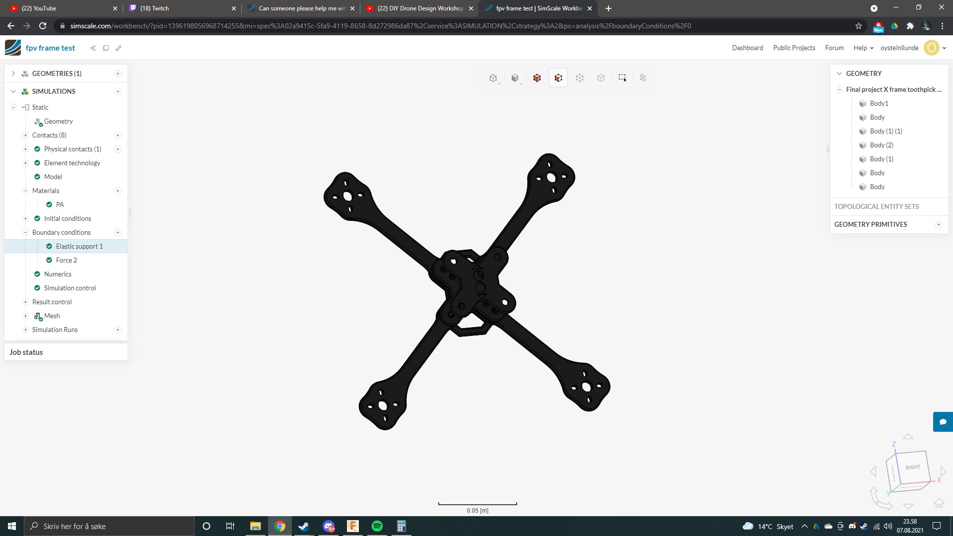
I took a quick look at your public project, fpv frame test, and it looks like you were able to get your simulation to run but I think you still have a few issues.
Your Physical Contact is not defined correctly and I am not sure what it’s purpose is. Currently it is not doing anything in the simulation. It looks like you have defined all faces of the geometry as the Master surface and nothing as a Slave surface.
I am not sure why Body1 is in the simulation. It is not connected to anything. If it’s not really needed I would remove it from the CAD. If your intent is to have the Physical Contact between Body1 and the rest of the parts then I am not sure this is the best way to do it.
I would also use a remote displacement instead of the soft spring option to hold the model.
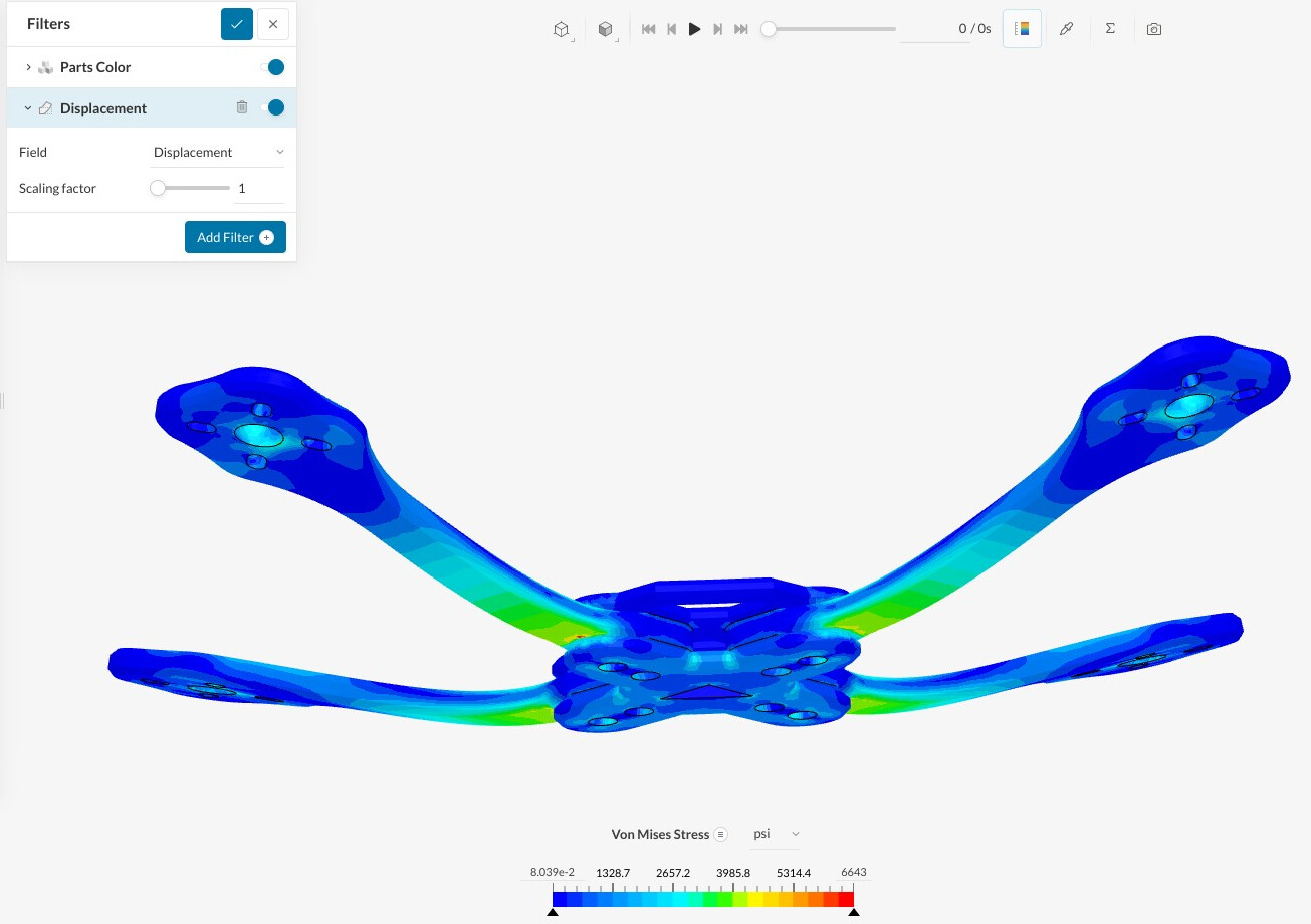
As far as how much stress the frame can take that depends on the material you are using. For example, if you are using Nylon 6 (PA6), the Yield Strength for that material is about 12,000 psi (82.7MPa). This is for ideal material conditions. To take into account 3D printed material and other flaws, you want the stress in your part to be less than about half the Yield Strength of the material, so around 6,000psi (41.3MPa). There are more detailed ways to a calculate this Effective Yield Strength, but this should be close enough for now.
In your model with the 10N force, the maximum Von Mises stress is 19psi (.13MPa) which is well below the Effective Yield Stress of 6,00psi. However, this will change once you fix the issues with your model.
I hope this helps. If not please let me know. If my understanding is not correct it could help to provide more details and maybe even a sketch of what you would like to accomplish.
Thank you and good luck!
Christopher
could you do a setup of my quad to do a stress test so i can see ? im unsure what to do… im a beginner as i said
id like to see how much force it can take
Hi @oysteinllunde,
Please take a look at this link.
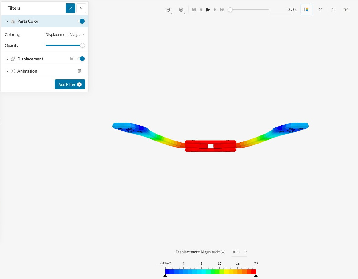
I used Remote Displacements to constrain the four locations where the motors would mount. Then I added a force to four points that I thought the weight of the batteries and electronics would be hanging from. I also multiplies the weight (estimated 5.5N) by 10 to account for maneuvering loads.
With these boundary conditions the Von Mises stress is 6,600psi which is about at the limit that you would want it. The deflection of the arms is 20mm, this could be more than you would want for a drone.
I hope this helps you out,
Christopher
Thank you so much for help!
so thats 5.5nm thats 56kilos when does it break? i wanted to test with carbon fiber thanks!
So with a 55N load the maximum stress using PA is 6,600psi. Beyond this point the arms should start to yield, meaning they will start to permanently deform. PA is not brittle like carbon fiber so it will permanently deform before it actually breaks. When the part starts to permanently deform is usually considered failure.
To test with carbon fiber you will need to change the material properties in the simulation and you will also need to know the yield strength.
I hope this helps.
Christopher