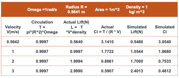
Please consider all the values in SI units for the table above. I have only added 2-3 runs in the link above, though I did the same for several other values by only varying incoming vel & rotating velocity.
Lift (Force): Newton (N)
Circulation: Square meter per second (m²/s)
Coefficient of Lift: Dimensionless
Spinning Velocity: Radians per second (rad/s) .
Incoming Velocity: Meters per second (m/s).
I am trying to simulate an incompressible flow around a 2D-spinning cylinder of area 1m^2, and validate the results against the theoretical values. I have included the formulae, and the actual and simulated results in the table.
I found out that correct results can only be obtained through the implementation of “Rotating Zones” which I have done here. However, it’s funny that my simulated values of Lift and Coeff of Lift, is exactly half of the expected values. What am I doing wrong?
Hello @athiram , thanks for posting your question here!
I also tried simulating your problem with a rotating wall approach (which is quite applicable for cylindrical bodies), however I could not improve the solution further.
Somethings you can do to improve the solution are:
I can see that the first layer thickness of the boundary layer cell is intended for y+ < 1. In this case, you would also need to change the wall settings to Full Resolution instead of wall functions
The transition between the boundary layer cells and the core tetrahedral cells is not really good. Please make sure you have enough number of layers in the boundary layer when defined manually, in order to make sure the transition between the last boundary layer cell and first tetrahedral core cell is as smooth as possible. Otherwise velocity gradients may not be computed effectively there, hence affecting your pressure/force computation on the surface.
I hope these would be helpful, let us know if these suggestions won’t solve your problem.
Hi @athiram: I took a quick look at your meshing and MRF preparation for that simulation. In My Magnus effect study I used TET mesh but I did pay attention to BL (as @kaany spots it in point 2). Your simulation domain looks like an overkill and can be 1000 smaller. Moreover I used Moving Wall in minimalistic domain setup, as my target was to compare different configuration of rotating cylinders.
Mind as well, that if 1000 iteration is way too high for that ‘tiny’ project and I suggest you set it to 100 steps first and that use ‘continue’ to another 100 steps. If ‘dust’ is already settled, you will see minimal perturbations in Convergence plot. That way you will save a lot of available resources.
I do not know if Full Resolution will save your day, but first focus on BL, please!