Great! Notepad++ is the best for manual concatenations of text files. By the way: MRF zone should be really in the vicinity of the propeller. Do not make it too big.
If it is a solution for your problem, please indicate it were appropriate.
Hi all, so yes, this post is to confirm that using STL exclusively seems to result in higher prism layer formation! Thanks again @Retsam
Details:
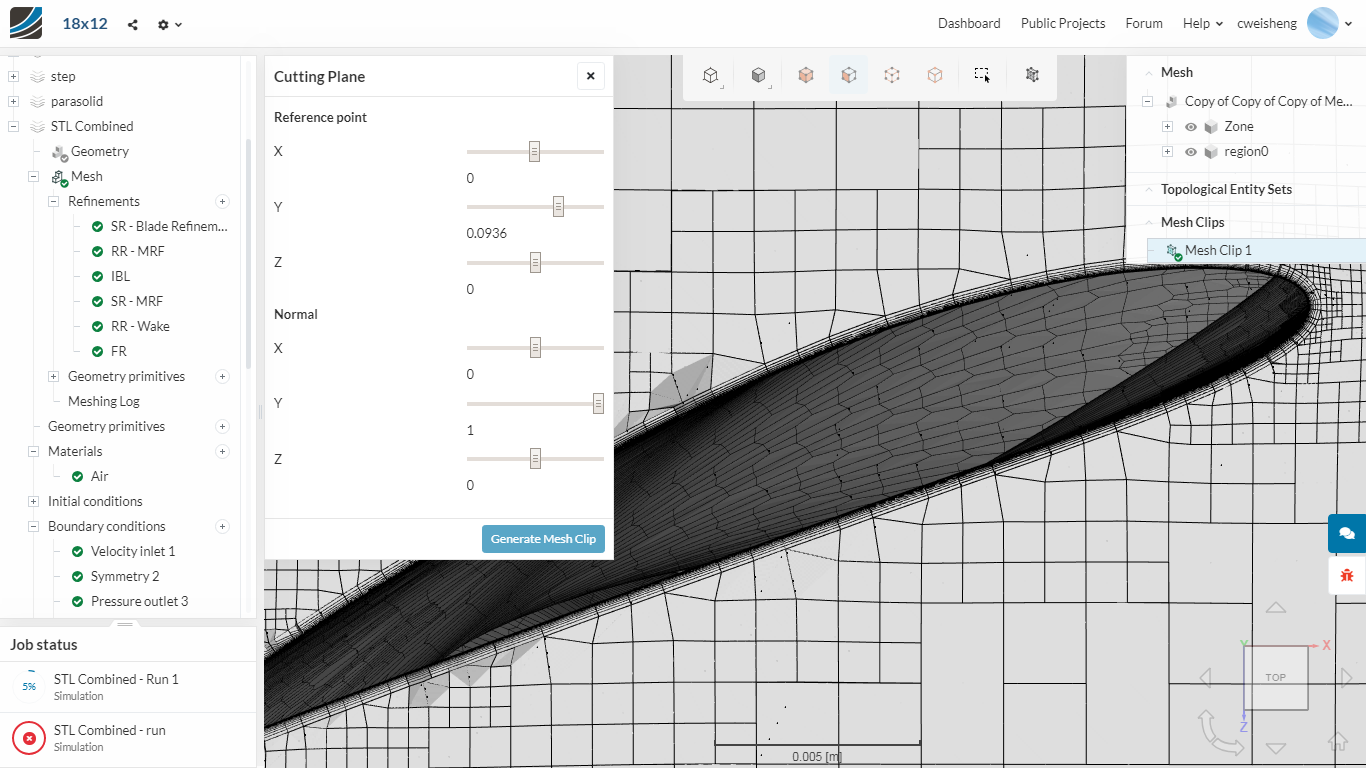
Objective of my current exploration was to conduct MRF simulation on propeller to see how well SimScale predicts the thrust and torque characteristics. Before I can do that, a decent simulation mesh needs to be generated and this post was a result of problems encountered at this stage.
As you would read above, there were several problems along the way, perhaps due to my inexperience with OpenFoam and SnappyHex. All along, I was working with IGES files and the best prism layer formation was about ~70% I would say (optimistically). I have tried both y+=1 and y+=100 types, 5 layers to >10 layers etc since the cause of the problems were not clear.
After almost giving up, and with very few options left (haven’t tried cfmesh as I don’t think my laptop has enough RAM), I just thought of trying STL. But I was not able to import 2 solids in 1 file if I directly output from Autodesk Fusion360. Nevertheless, the prism layer formation was >90% for meshing without the MRF volume.
Luckily @Retsam replied my distress call on STL and I managed to combine 2 STL files by exporting them in ASCII format and copying and pasting one STL file to another using Notepad++. Great idea! You will have something like that:
solid PROPELLER [this is the 1st STL file]
facet normal -8.195655e-01 5.663210e-01 8.713685e-02
outer loop
vertex -1.877391e+01 1.240122e+01 8.000000e+00
vertex -1.874856e+01 1.238448e+01 8.347296e+00
vertex -1.796457e+01 1.354920e+01 8.151286e+00
endloop
.
.
.
endsolid
solid MRFVOLUME [this is the pasted-in 2nd STL file]
.
.
.
endsolid
And then save as “All Files” with the .STL extension. Then proceed to import into SimScale.
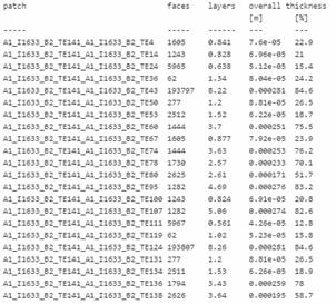
With the MRF volume inside too, it works! Again, >90% of the prism layers generated:
solid_0_PROPELLER 297213 9.97 0.000308 92.7
I used very fine tessellation on the propeller (and reminder to self to scale down by 0.001 to work in m).
Your welcome! However credits should go to @Get_Barried, @anirudh2821998 as topic is about meshing. I simply took a look at STL file handling, which is nothing compared to meshing complexity!
Different geometry, same problem (if not worse). Now, even the high y+ mesh PL is problematic (0.2% formed), following all the previous settings and tricks.
SimScale sales contacted me to ask about converting to Professional plan… no news heard after I shared the pain points.
Jousef, I wanted to confirm, exporting as STL instead of importing directly fom Onshape is still the recommended path? It would be great if Simscale did this by itself