Hi all, so yes, this post is to confirm that using STL exclusively seems to result in higher prism layer formation! Thanks again @Retsam
Details:
-
Objective of my current exploration was to conduct MRF simulation on propeller to see how well SimScale predicts the thrust and torque characteristics. Before I can do that, a decent simulation mesh needs to be generated and this post was a result of problems encountered at this stage.
-
As you would read above, there were several problems along the way, perhaps due to my inexperience with OpenFoam and SnappyHex. All along, I was working with IGES files and the best prism layer formation was about ~70% I would say (optimistically). I have tried both y+=1 and y+=100 types, 5 layers to >10 layers etc since the cause of the problems were not clear.
-
Y+=1 mesh will be something like:
Layer1------3.40E-06m
Layer2------4.42E-06m
Layer3------5.75E-06m
Layer4------7.47E-06m
Layer5------9.71E-06m
Layer6------1.26E-05m
Layer7------1.64E-05m
Layer8------2.13E-05m
Layer9------2.77E-05m
Layer10----3.61E-05m
Layer11----4.69E-05m
Layer12----6.09E-05m
Layer13----7.92E-05m
Layer14----1.03E-04m
Layer15----1.34E-04m
Layer16----1.74E-04m -
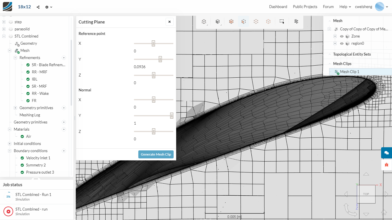
After almost giving up, and with very few options left (haven’t tried cfmesh as I don’t think my laptop has enough RAM), I just thought of trying STL. But I was not able to import 2 solids in 1 file if I directly output from Autodesk Fusion360. Nevertheless, the prism layer formation was >90% for meshing without the MRF volume.
solid_0_stl_solid 293784 10 0.000309 93.1
Aside: Using STEP file, the formation was ~70+%.
A1_I1541_B2_TE141_A1_I1541_B2_TE43 193864 7.83 0.000262 78.9
A1_I1541_B2_TE141_A1_I1541_B2_TE50 277 0.17 1.3e-05 3.93
A1_I1541_B2_TE141_A1_I1541_B2_TE53 2524 1.19 4.62e-05 13.9
A1_I1541_B2_TE141_A1_I1541_B2_TE124 193794 7.83 0.000262 79
A1_I1541_B2_TE141_A1_I1541_B2_TE131 277 0.17 1.3e-05 3.93
A1_I1541_B2_TE141_A1_I1541_B2_TE134 2523 1.19 4.62e-05 13.9
- Luckily @Retsam replied my distress call on STL and I managed to combine 2 STL files by exporting them in ASCII format and copying and pasting one STL file to another using Notepad++. Great idea! You will have something like that:
solid PROPELLER [this is the 1st STL file]
facet normal -8.195655e-01 5.663210e-01 8.713685e-02
outer loop
vertex -1.877391e+01 1.240122e+01 8.000000e+00
vertex -1.874856e+01 1.238448e+01 8.347296e+00
vertex -1.796457e+01 1.354920e+01 8.151286e+00
endloop
.
.
.
endsolid
solid MRFVOLUME [this is the pasted-in 2nd STL file]
.
.
.
endsolid
And then save as “All Files” with the .STL extension. Then proceed to import into SimScale.
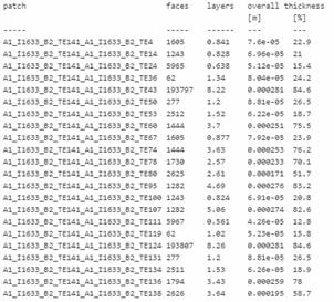
- With the MRF volume inside too, it works! Again, >90% of the prism layers generated:
solid_0_PROPELLER 297213 9.97 0.000308 92.7
I used very fine tessellation on the propeller (and reminder to self to scale down by 0.001 to work in m).
Now, I can finally run the simulation knowing that I have a decent mesh. Hopefully.
Thanks @DaleKramer, @Get_Barried and @Retsam for the help.