Hello everyone, very new to all this. I’m modeling airflow through a body and I have one surface of my model that isn’t really a surface in reality. There is a much bigger volume after, It’s a dead end in and not only impractical to model, but unnecessary in this case. However to have this boundary as a surface is inaccurate. In thermal modeling I would call it adaibatic, what boundary condition should I assign?
Hi @hlansdowne,
Thanks for posting your question. Could you please share the project link with us?
best,
here you go. it’s the surface at the opposite end of the inlet.
Hi again @hlansdowne,
r this incompressible simulation, a non-slip wall boundary condition should be the best choice. As I see that you are not setting nothing to this referred surface, SimScale automatically sets it as non-slip wall, so no worries about setting it again.
Here you have more info about it.
best,
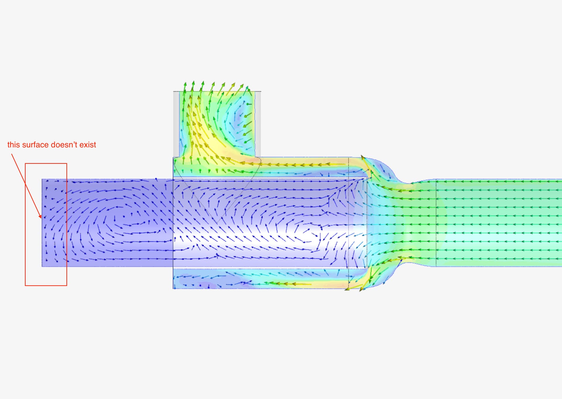
thanks goncalves, but i’m dubious about the results. in the pic you can see that the airflow is being affected by a non-existent surface
Not quite sure what you are trying to model, but I don’t see how any air should be expected to exit that 0Pa pressure outlet if you are forcing the same amount of air that flows into your Velocity inlet to go out your Velocity outlet.
EDIT: I must have looked at your project after you set the pressure outlet to 0Pa and before you ran another simulation. What BC was the left outlet set to when you made your 1st image of this topic?
Got it. In this case that this surface that doesn’t exists it can be treated as an open surface/outlet. In this case setting Pressure Outlet BC as 0 seems to be fair, but as Dale has pointed, make sure to check about your Velocity outlet BC at first, which is forcing the same amount of air.
I think you must assume that both outlets are non zero Pa pressure outlets. It is up to you to input these two pressures at values that you expect, or measure in a real world setup. (or divide the flow between them appropriately)
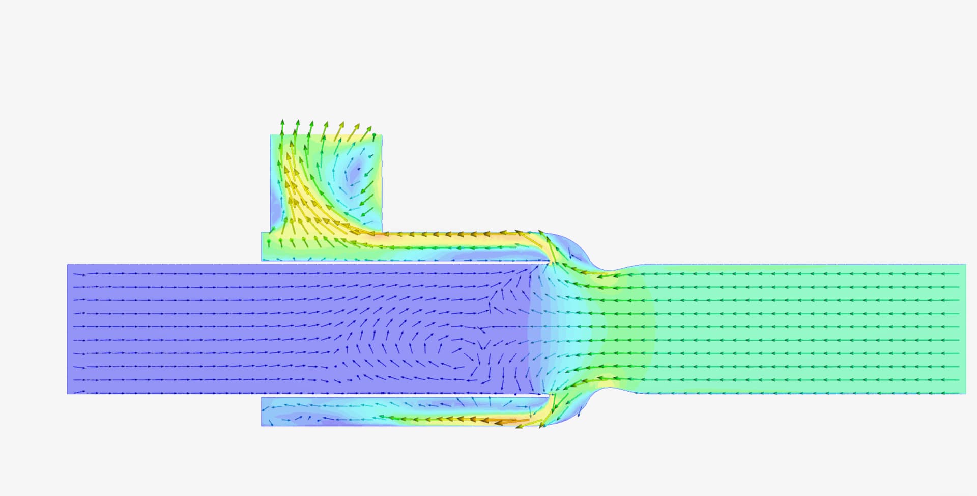
I just tried setting it as a pressure outlet and set it to 0 Pa, but i get an odd result. i get vectors emanating from the outlet but i guess this makes sense since there is likely no truly stagnant air in this case? does this look correct to anyone?
You could look at the speed of the air at the pressure outlet which I think should average to 0.
EDIT: I do not think you are able to easily make this device in real life to get equal flow on your 2 velocity IN/Out faces without putting a physical cap on the left face.
There will be a cap on the “tube” on the left, but it will be a large airtight box and the airflow in that box is not relevant so it’s not modelled. i just need to get a sense of what the flow would look like at the throat with such a dead end. i expect i may get some oscillation but at this point i’m not concerned.
Actually, that airtight box would affect how the vortices would likely set themselves up in the tube leading up to the 0Pa pressure outlet you now have.