Hi ,
I ran simulations of the same geometry, with identical material assignments and boundary conditions: one in CHT and other in CHT v2.0 (materials are assigned a bit different, but it should be the same).
The problem I’m solving is cooling of electric motor with water spiral (coolant) running along the circumference of the motor. I impose some power losses to the stator and windings of the motor and want to check the stationary temperature.
The problem is that for the CHT v2.0 the maximum temperature is around 130 degC, and for CHT is around 68 degC, which is a huge difference and now I’m not sure which one is correct, if any is. The 130 one seems more reasonable to me but I’m not sure. These simulation were done for initial temp of the model of 65 degC.
For the CHT simulation, I also tried setting the initial temperature of the whole model to 80degC, and then the maximum becomes 83 degC. So now, I’m really not sure what is happening since the initial temperature changed the result so much.
Based on the residuals it seems to me that the solution converged enough for both CHT and CHT v2.0.
I would use CHT v2.0 for everything, but now I want to simulate more fluids in the model which I can’t do with CHT v2.0, so can someone please advise me on what to do.
I put them in different projects.
Links to projects: CHT V2.0: SimScale
CHT: SimScale
Many thanks!
Hi @markomatisic, I’ve got a couple of things to review:
-
Did you perform a 0-dimensional mass-energy balance? What is the expected result?
-
Clearly there is a difference between the set-up of both models. CHT2 gives an option for weakly compressible flows (for example natural convection) that is carried using the boussinessq approximation (for buoyancy). My question is: Does a highly convective flow with significant temperature differences behave under this approximation? In addition, thermo is set differently for both cases, as far as I see. For CHT you have h-const. For glycol, given your temperature difference, you can have a 15% difference in the heat capacity.
-
The cases have very fine meshes. I am having trouble postprocessing them. It would be nice from you to provide some images showing the difference in the results and where is it located.
-
It is difficult for me to say more as I am not sure which equations are being resolved in each case. My guess was based on the standard solvers of OpenFOAM.
2 Likes
Hi @jairogut, thank you for replying
-
I did not, can I do that automatically somehow within SimScale? And just to make it clear what you mean by mass energy balance - the total power sources in [W] should equal the fluids P = (mass_flow_rate)c_p(T_outlet - T_inlet)?
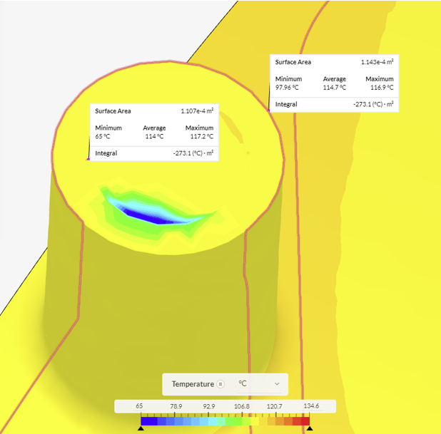
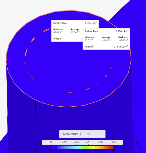
If so, I did it for the last iteration from the outlet average temperatures in the figures below and T_inlet = 65 degC
For CHT V2
CHT V1
Calculating it by hand(with constant c_p) the average temp at the outlet should be T_outlet = 69.5 degC meaning none of the results are fine and satisfy the energy balance. Please confirm if I did this right and what to do in this case, I’m quite new to CFD.
-
It could be that it doesn’t behave this way but I can’t select anything else except hConst for CHT simulation. For CHT2 I can switch it to compressible but then I have to again select hConst. Do you think this would produce more reliable results?
-
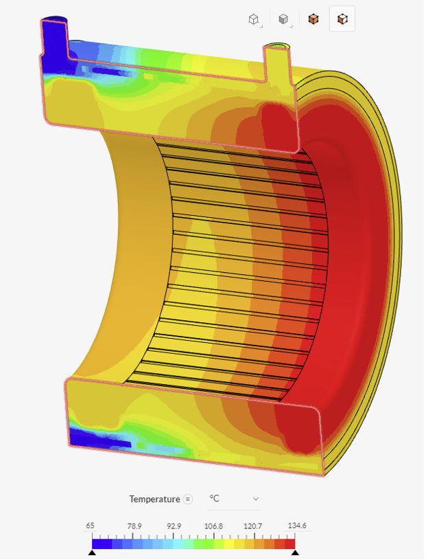
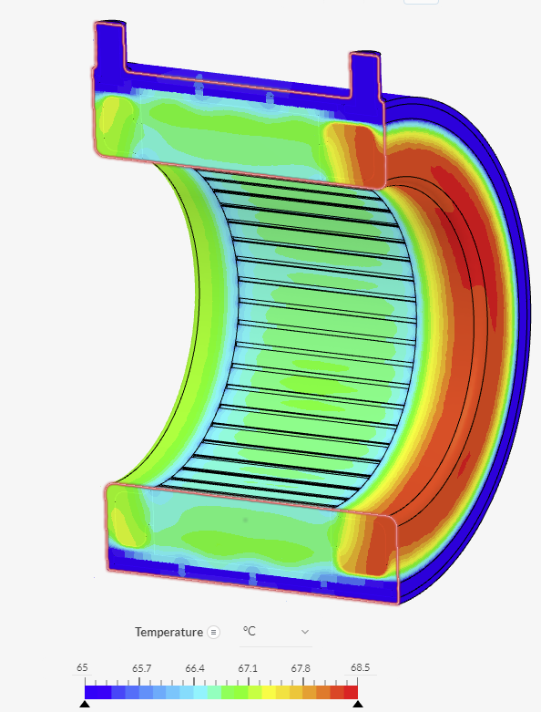
Additional images
CHT2
CHT
CHT one doesn’t look right to me, the fluid doesn’t heat up at all and the temperatures of all parts are low.
Thanks in advance.
Hello,
From a visual inspection, it looks like the CHTv1 results are likely far from converged at this point. Have you been monitoring quantities of interest to evaluate convergence (e.g. the temperature at the outlet)? How to Check Convergence of a CFD Simulation? | SimScale
Cheers
1 Like