That is correct, but software seems to use left hand rule, axis your thumb is pointing to (direction) is > than origin. Normally it also should be enough to specify any set of points in a space along rotation axis.
If you rotates along Z axis (X,Y being 0), 0, 1 points toward Z POZ. 100, 101 or -101, -100 on the Z axis does the same.
However I was completely misled by my cylinders rotating in both directions in any case they were shifted in X and / or Y axes. As Ruben said that ‘they are working on it’ I stopped to experiment with that setting awaiting the fix. As precaution I decided to define a rotating axis of MRF zone as ‘piercing’ that zone, even if it was centered on 0 of an axis. Sounds like superstition I dislike, but I need this fix first.
In meantime I possibly discovered another problem in CFD, but will tell you in a different thread.
Not up-to-date what you have discussed so far but very flourishing conversation I have to say Just so that you know. It is the right-hand rule that is applied for MRF and notleft-hand as assumed. Can someone tell why you think it seems to be left-hand? Could be that the geometry is flipped and wrongly inclined/oriented.
I am not sure this example backs up your above statement.
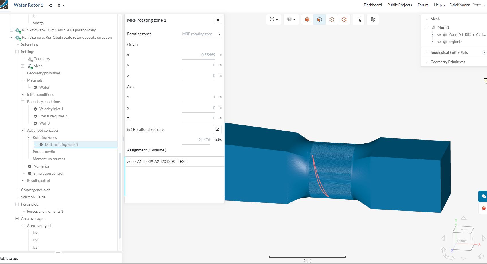
In my sample project I created for this pump, here we have Run3 MRF parameters (note the +ve rad/sec value) and the resulting head was -ve and the magnitude was near experimental results:
In Run 1 here are the MRF parameters (note the -ve rad/sec value) and the resulting head was +ve and about 10x the actual magnitude of the experimental results:
@jousefm: I suggest the problem of MRF rotating zone in BOTH directions is fixed first. Bottom line is that you are 50% right. Example I provided, is just an exception as 100% of MRF zone rotates in wrong direction.
 Just so that you know. It is the right-hand rule that is applied for MRF and not left-hand as assumed. Can someone tell why you think it seems to be left-hand? Could be that the geometry is flipped and wrongly inclined/oriented.