It should be fine then!
Well I usually do that by downloading the mesh and viewing it offline in ParaView. Unfortunately that isn’t an option for you.
It should be fine then!
Well I usually do that by downloading the mesh and viewing it offline in ParaView. Unfortunately that isn’t an option for you.
Hello there,
Please pay attention to coordinates of MFR zone. I experimented for a while with multiple MRF zones and discovered ‘half-rotating’ or even ‘rotating in both (+ / -) directions’ MRF zones. Setting probes points and observing velocity vectors convinced me about reality of those ‘impossible’ objects. For the moment, you can handle only one MRF zone and it should be centered on one of axes. Problem is reported and Ruben repeats that they are working on it.
Hi @DaleKramer,
I would rather say ‘fortunately’, as currently multiple MRF zones seem unmanageable. Correct setting of one MRF zone ‘just’ needs to aline center of rotation on ‘0’ of one of the axes. In you big setup it may be a bit tedious.
Moreover, when running simulation, I suggest you start to ‘load’ your turbine gently, using CVS file with progressive rad/s definitions. Otherwise you will have ‘exploding’ behaviour, such an amount of initial energy will dissipate slowly and reaching a steady flow would need 5-10 times more time of simulation.
Wow, I will try that with the nose of the rotor spinner at 0,0,0… Thanks,
And, the gentle loading after that…
Perhaps I should say ‘center of rotation’ ALONG 0 of one of axes. Example: base of your MRF cylinder can be at Z 0 m, top of cylinder at Z 2.0 m (if rotation axe is ‘Z’). You can, but do not need to align ‘geometric center’ of MRF zone to 0,0,0.
For ‘load’, try to go with ‘parabolic’ curve, which is good enough to not break you virtual setup.
Progress Report - No much luck yet
I created a new project and created my own mesh and simulations from scratch after I modified and imported the original ‘axial’ geometry file in RHINO.
Geometry changes made in Rhino (named ‘axial-DaleFan1p466m-new0’):
In the SimScale project:
I created a mesh on my new geometry using the same refinements as Mesh 19 in the original project.
I made 2 simulation runs in my simulation named ‘Incompressible’.
Results:
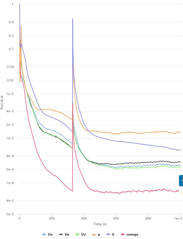
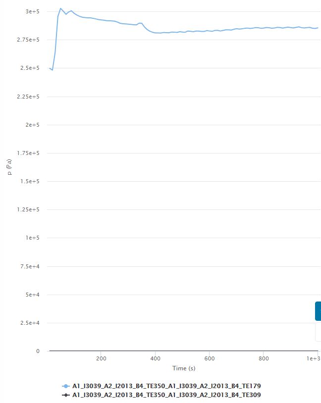
Run 1: No significant change in Head, head is still 285,000 Pa with this convergence and pressure plots:
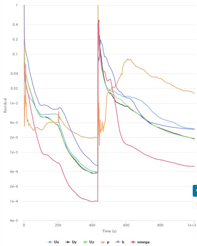
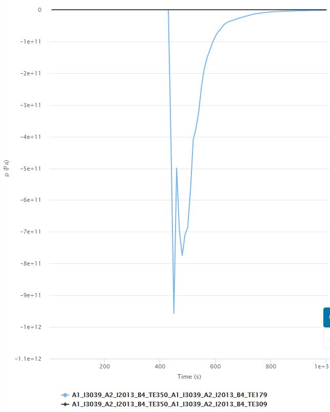
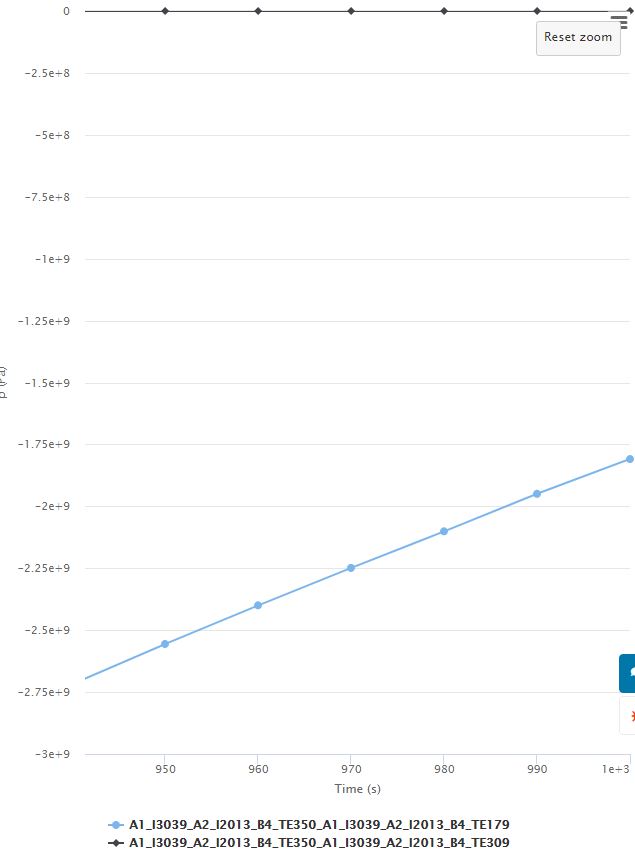
Run 2: Significant convergence issue appeared and Head was not stable at end of run with this convergence and pressure plots:
Where to go from here:
Someone should look at the mesh quality in Paraview (I can not run Paraview with my video card).
I have found something other than simply ‘the Head is incorrect compared to the results’, which may give more clues to what is happening here.
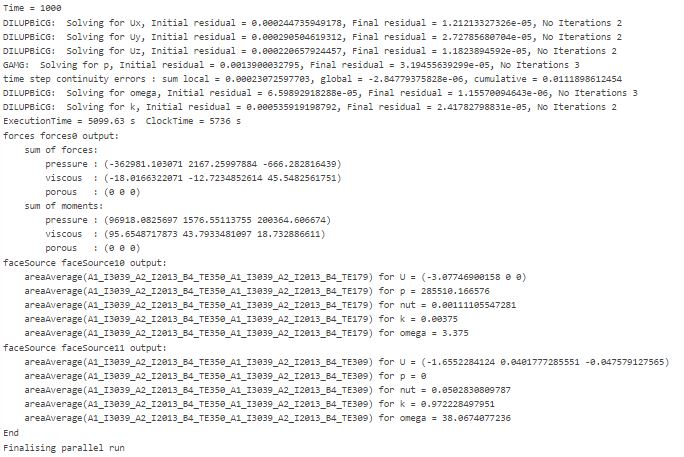
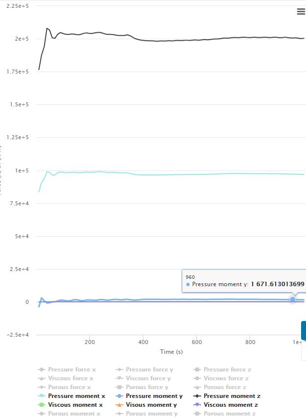
If you look at the ‘Forces and Moments 1’ results from Run 1, on all the faces of the spinning rotor, they don’t make sense to me:
As far as all moments about the center point of the MRF volume (that is the point I chose for the ‘Forces and Moments 1’ calculations), I would only expect to see a moment about the rotational axis (x) and the others should be 0 (I think). So why is the total pressure and viscous moment about the x axis direction ~97,000 Nm while the total z axis moments is ~200,000 Nm and the y axis ~1,600 Nm?
I’ve gone about as far as I can go and I will continue after @robnaz answers my Post 9 here and my Post 16 here ![]()
AND, hopefully someone else can help further…
Dale
Two things, @DaleKramer:
You have two sources of ‘inertial load’ into your pump (I did not know it before going to the project, now). You did apply ‘pacing load’ on your inlet but you started your turbine at full speed. It is an obvious mismatch, you can fix. By chance your setup keeps now for 430 seconds and blows afterward. So please disregard everything after 430 seconds of simulation, as it is completely off and cannot recover (so question about total pressure on other axes after 430 seconds of simulation is irrelevant) .
You will always find fluctuations on other axes than a rotation one. Those pressure forces should be < 0.1 %. I see pressure force on Z axes develop to over 0.2 % from 380 seconds on of simulation but one cannot be sure about it’s origine.
May I bring your attention also to ‘Forces and moments’ you defined which are centered on Y axe, ‘-0.55669’, for all blades, that seems incorrect, as you rotate on X axe.
Bon courage!
Retsam
Please correct me if I am wrong, but my understanding is that the point which you choose for ‘Center of Rotation’ in the ‘Force and moments’ results is that it can be defined anywhere in the whole coordinate system. I think of the force and moments results that we get are simply the force and moments that would have to be applied at that point to hold the geometry selected in ‘Forces and moments’ at that time interval. I know this would require some invisible, rigid, mass-less structure that connected that point to the geometry selected, but once you have the results for that point, you can just translate the moments to some other point that actually holds those faces in real structure that is missing from the CAD (no support structure for rotor).
I put that point at the ‘center point of the MRF volume’ and in doing so it led me to my ‘Where to go from here’ question about moments that have to be applied about that ‘center of rotation’ and my query about why there are z and y axis moments when intuitively, my brains says those should be close to zero about that center point…
These moments are not fluctuations but are pretty stable through the last few hundred time steps as you can see in my images.
I will also additionally bring the rotational speed up parabolically in a yet to be, Run 3…
I see your point, but perhaps somebody would need to jump in that "Forces and moments’ setup on multiple, not connected bodies. I also make possibly invalid assumption about ‘geometric center’ of that assembly of blades.
One more point is that I would add separate ‘sensors’ to inlet and outlet in order to be able to observe the discrepancies…
Since the head is determined by the difference in pressure between inlet and outlet, and the outlet has a boundary condition of 0 Pa, we only need an area average on the inlet to determine head.
But we already have a ‘Surface Data’>‘Area Average 1’ acting on both the inlet and outlet faces (results the same as just inlet face since outlet face is 0 Pa)
You can see the 2 area averages plotted in the 2nd graph shown in my post above under ‘Results’ Run 1, below the convergence plot…
BINGO !! 

While I was making the parabolic csv data to ramp rpm up from 0, I was just looking at the mesh and coordinate arrows and BINGO.
SO, I think the pump was rotating backwards… I believe the direction of rotation in rotating zones is with respect to the faces you select to rotate in the zone and then you apply the right hand rule to that vector you define (with thumb of right hand point in vector direction, +ve rotation is in the direction that your fingers wrap around the vector)…
I am running a ‘Run3 same as Run 1 but rotate rotor in the opposite direction’.
It is only 1/2 done but is converging much better that all other attempts and the head is about 0.12 meters.
I am sure that by developing a mesh with fewer illegal faces, adding the other structure in the duct, layering the geometry and fine tuning the simulation parameters that you will get very close to the 0.26 meter experimental result.
Another clue should have been the sign of the pressure of 285,000 Pa on the inlet I think we should see a -ve value.
I will let you continue from here…
That I understand: I said ‘sensors’ instead of ‘probes’ in space before and after rotating zones. This would give idea of fluid movements in that idea.
Good news: @jousefm also confirmed, some time ago, the right hand rule when asked, which I quickly invalidated with my MRF zones experiments. And forgotten. As of today, left hand rule is used by software. But now, if it is fixed, all previous simulation will fail, if restarted.
Hi @DaleKramer,
Firstly, thanks for the help!!
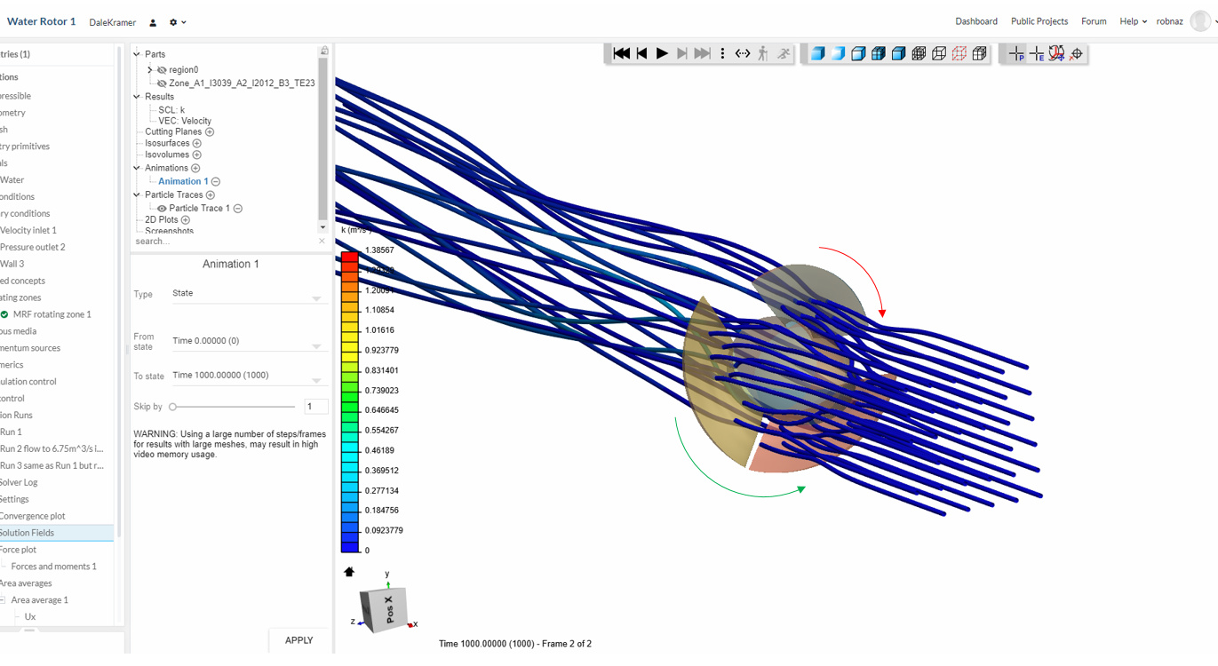
Please correct me if I am wrong, but following the ‘right hand rule’ the green arrow showing below is the vector direction that you defined in your last run, right? But the real rotor direction is represented by the red arrow below… What can you say to me about that? Am I wrong in my consideration?
Thanks for all participating in this project!!!
Best,
Roberto Nazareno.
If the rotor rotates in the red direction, it will push water towards the inlet, would it not?
Hi @DaleKramer,
Look at this example,
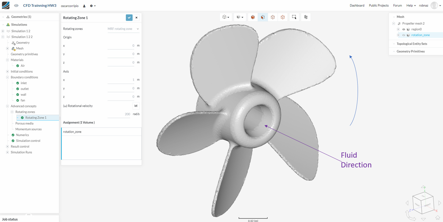
The ‘+’ direction is given by the angulation of the blades. In my case, the blades are in the opposite inclination, can you get it? Therefore, for the same direction of the fluid flow, it is necessary that the rotation be in the ‘-’ direction. Please, am I wrong?
Best,
Roberto Nazareno.
From what I see, that new rotor in post #37, when spun in the blue rotation direction will move water in the -ve fluid direction.
Hi everyone,
The project will be finished and all merit must be given to @DaleKramer, @Get_Barried and @Retsam. Many many thank you guys!! Thank you SimScale!!
Best,
Roberto Nazareno.
This is a little confusing to me.
Just to confirm, I believe that currently the software uses the right hand rule around the defined ‘Axis’ vector BUT the direction polarity is with reference to the direction that you want the geometry in the selected volume to rotate, am I correct?
Thanks,
Dale