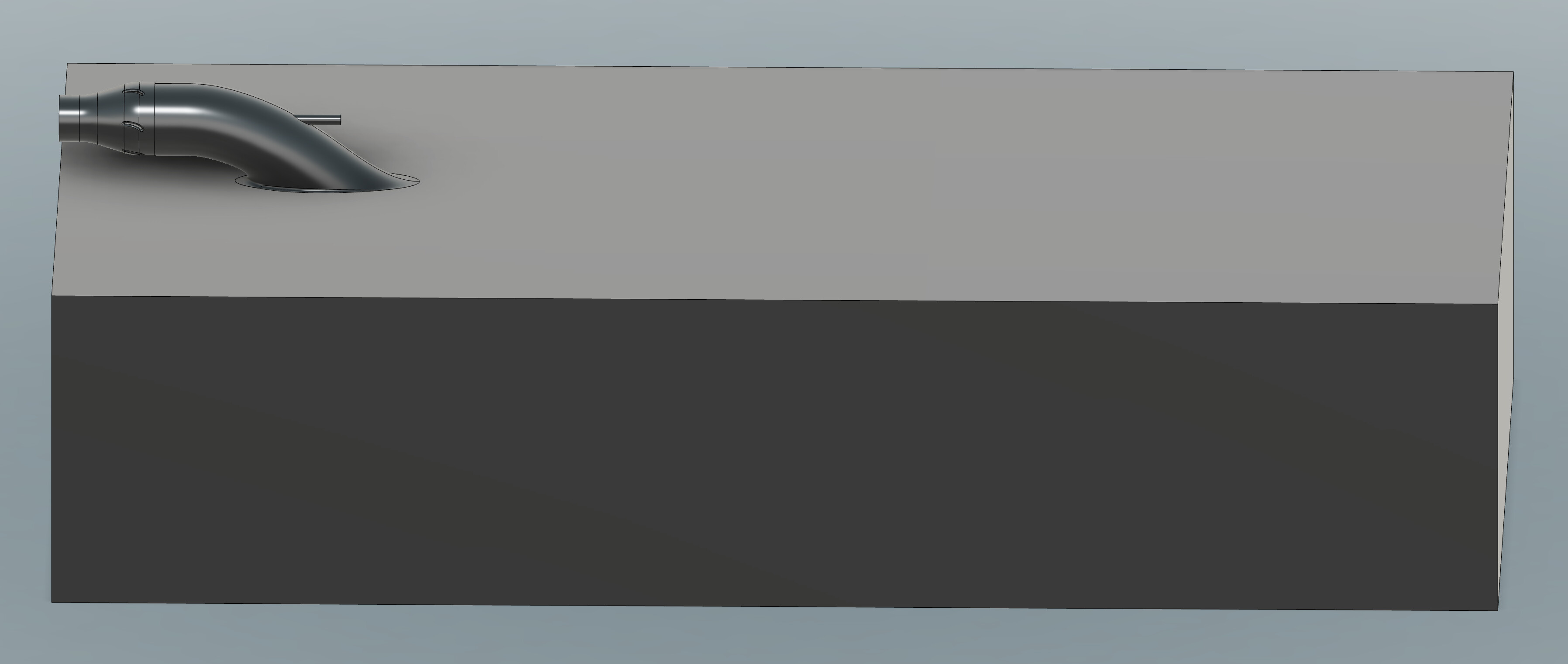
I am having an issue with meshing an axial flow pump I have designed. This is the gen 2 design where I have setup a boundary box to represent incoming flow (think of a jet ski on water, the box is the free stream water).
Link to gen 2 project: https://www.simscale.com/workbench/?pid=4275774943384078413&mi=spec%3Af54f6baa-09af-4498-ad31-5c1011fcbdcf%2Cservice%3AMESHING%2Cstrategy%3A13&sh=7
I have ran CFD on a gen 1 design design without the incoming flow boundary box and it meshed fine.
Link to gen 1 project: https://www.simscale.com/workbench/?pid=3947993680400786834&mi=spec%3Aa069fb6f-7c32-41e0-a836-812d3210c781%2Cservice%3AMESHING%2Cstrategy%3A6&sh=5
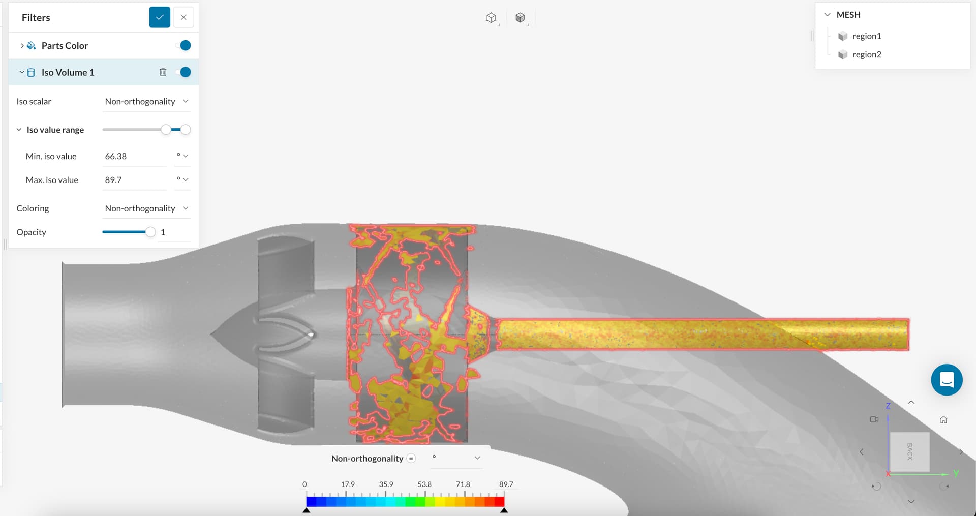
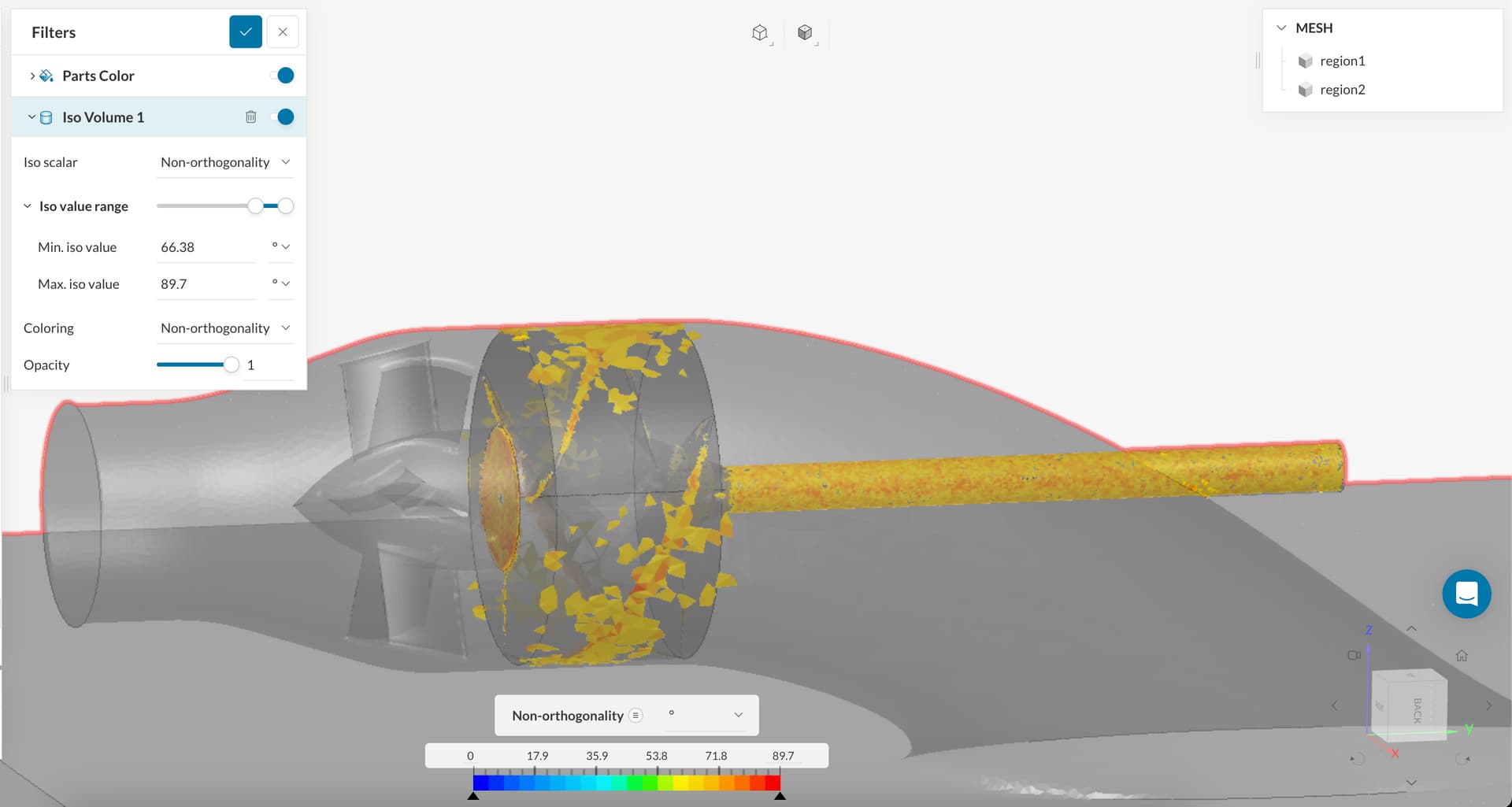
Issue: When meshing my gen 2 setup, I am getting non-othrogonality issues:
I have tried 3 different meshes to see if I could improve it.
Mesh 3: everything kept the same as gen 1 mesh settings
Result: CFD simulation diverged.
Max. Non-orthogonality: 89.4
Number of cells with Non-orthogonality > 88 deg: 512
Mesh 1: everything kept the same as gen 1 mesh setting, but increased mesh fineness to 7
Result: worse
Max. Non-orthogonality: 89.4
Number of cells with Non-orthogonality > 88 deg: 543
Mesh 2: everything kept the same as gen 1 mesh settings, but created more local element refinements (the impeller blade tips and sides, the stator leading edge, the pump inlet where it meets the water surface, and the area between the impeller and stator since there is a fine gap there.
Result: even worse
Max. Non-orthogonality: 89.3
Number of cells with Non-orthogonality > 88 deg: 787
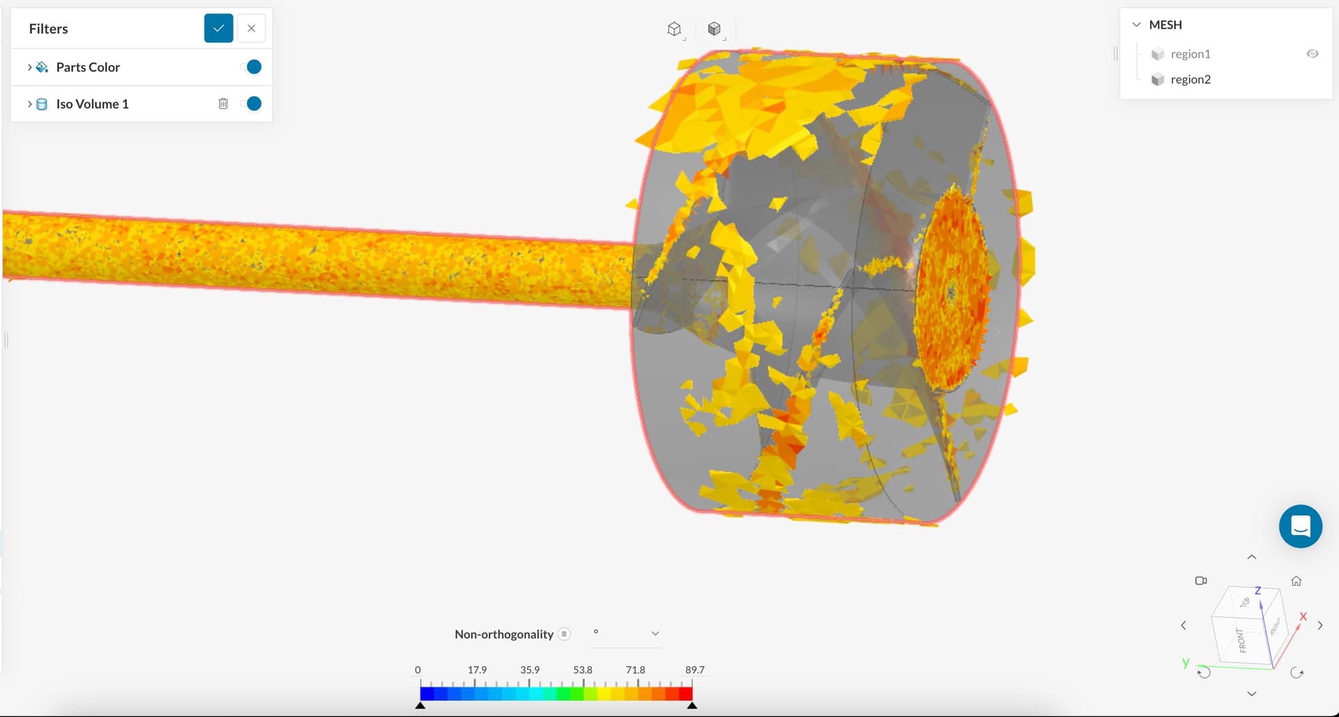
Unsure of what is causing the issue. After reviewing the mesh using the mesh quality checker, I can see the non-orthogonal cells. The aspect ratio and edge length inspections look fine, however the logger shows really high maximum values.
I am trying to understand what is causing this. I know sharp edges and gaps are an issue, but the gen 1 model has the same gaps and sharps corners in the same spots. The only thing that has really change (aside from some slight geometry differences) is the addition of the water box boundary.
I can “clean up” the CAD model if needed, but unsure of what to clean up. Any help regarding this would be much appreciated.
Thanks!
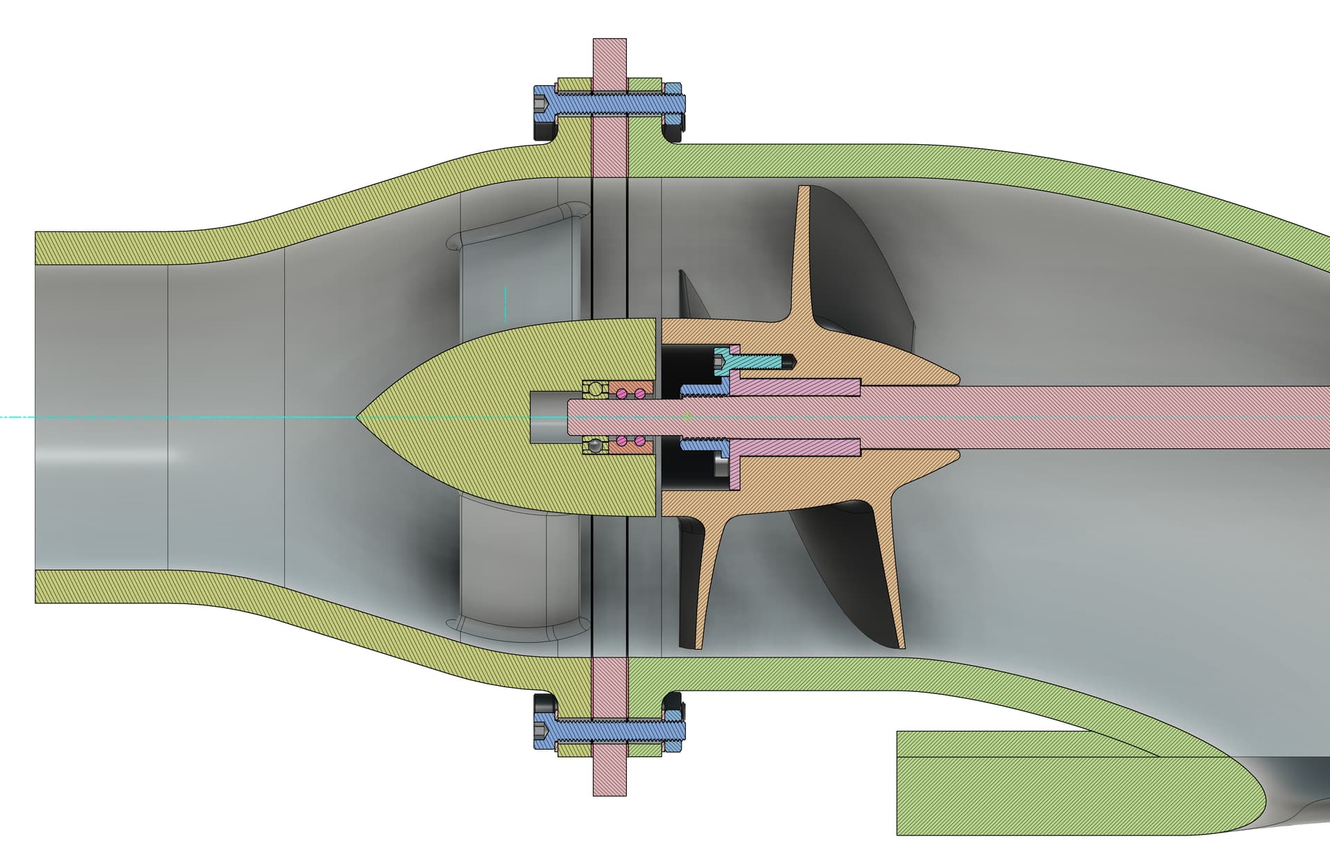
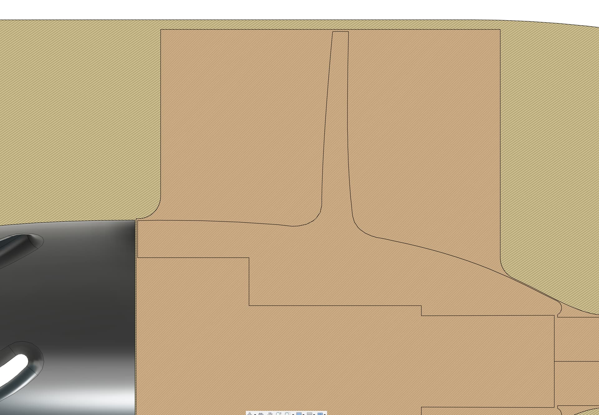
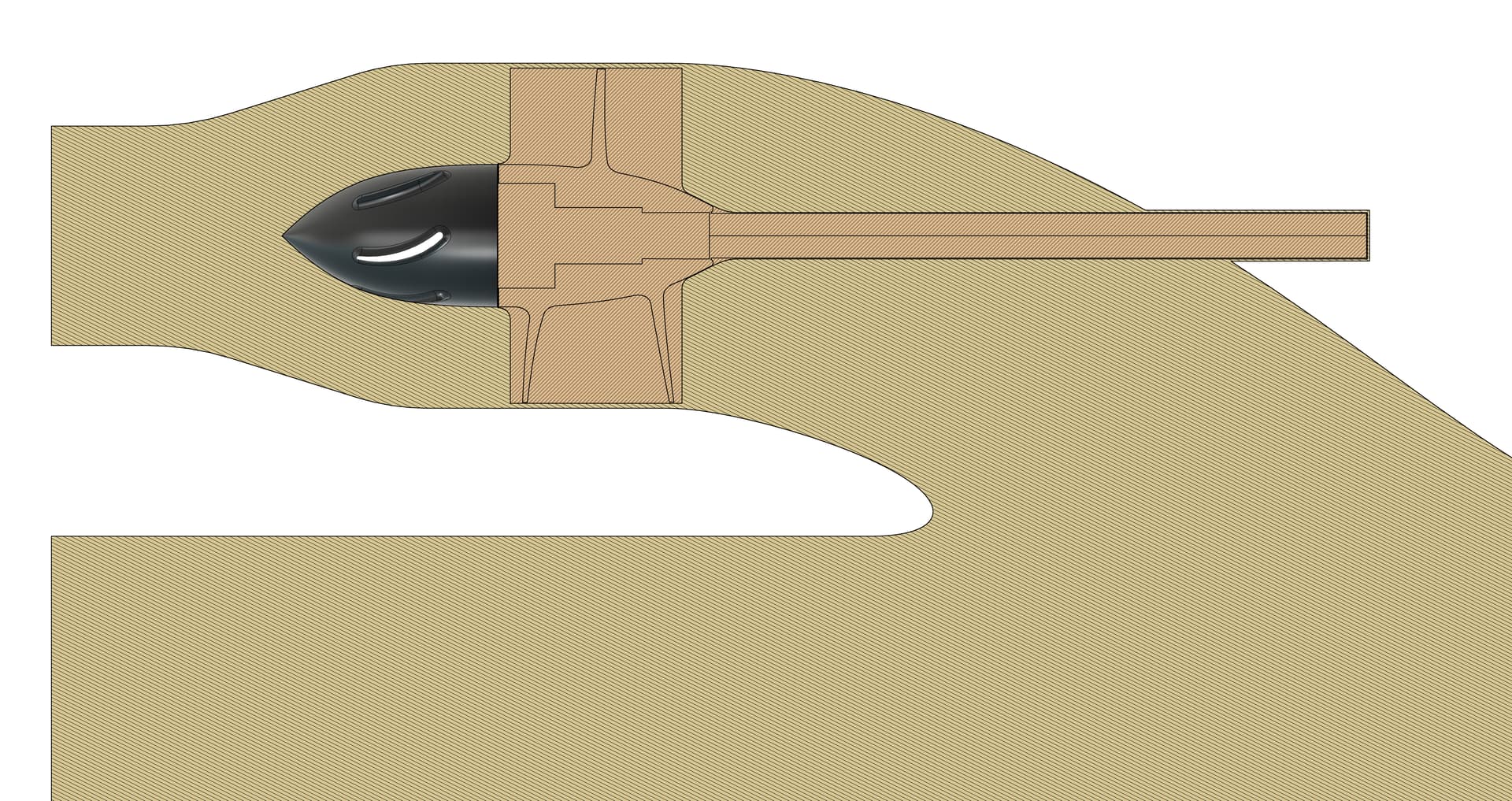
Pictures of the CAD Assembly as well as the flow simulation model to see clearances/gaps. The rotating zone is 0.2 mm off the impeller as taught in the centrifugal pump tutorial.