i am new to this simulation process and this is my first attempt with a model drawn by me by referring to a journal .
JOURNAL LINK : https://doi.org/10.1016/j.jestch.2018.05.016
i am doing this simulation setup for validation purpose,so that i could say (in my project presentation at university that) i can do a simulation regarding this topic and i can generate results for a new model which i will be drawn by modifying certain values or changing certain parameters of the given turbine model…in short, i need correct results. (which is little difficult for me as i am new to this).
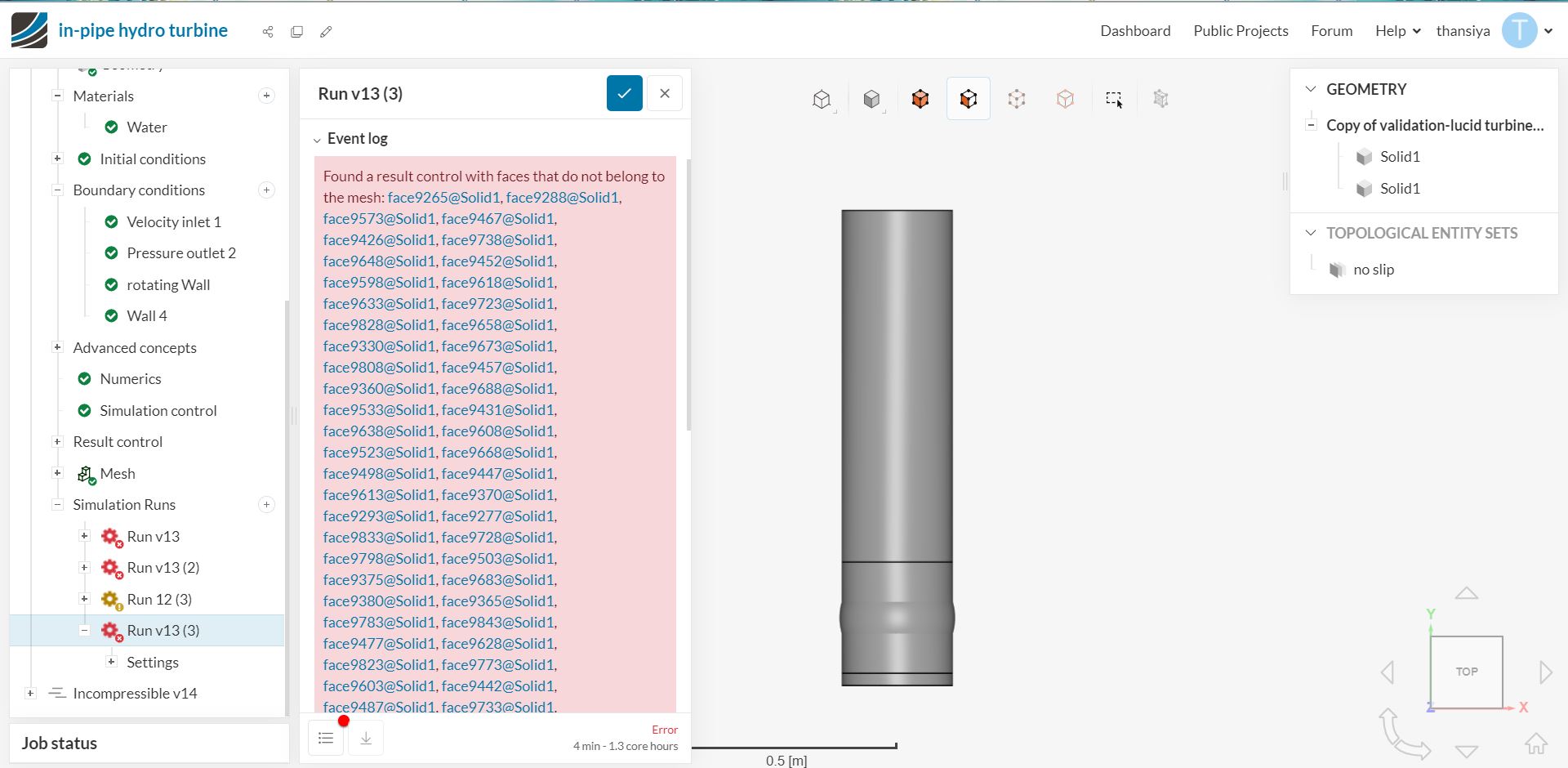
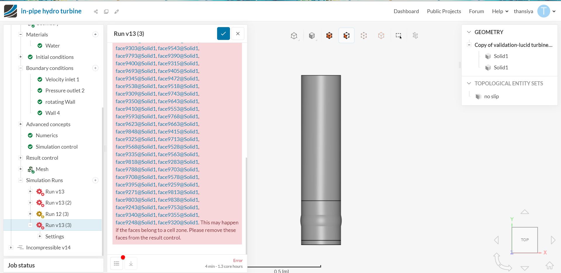
while i was doing my simulation, i got an error saying “A setup with 2 regions is being used in a single-region analysis type. Please make sure that all regions except for one have an Advanced Concept assigned to them.”…i looked in forums , but in vain i couldn’t do much. I couldnt understand.
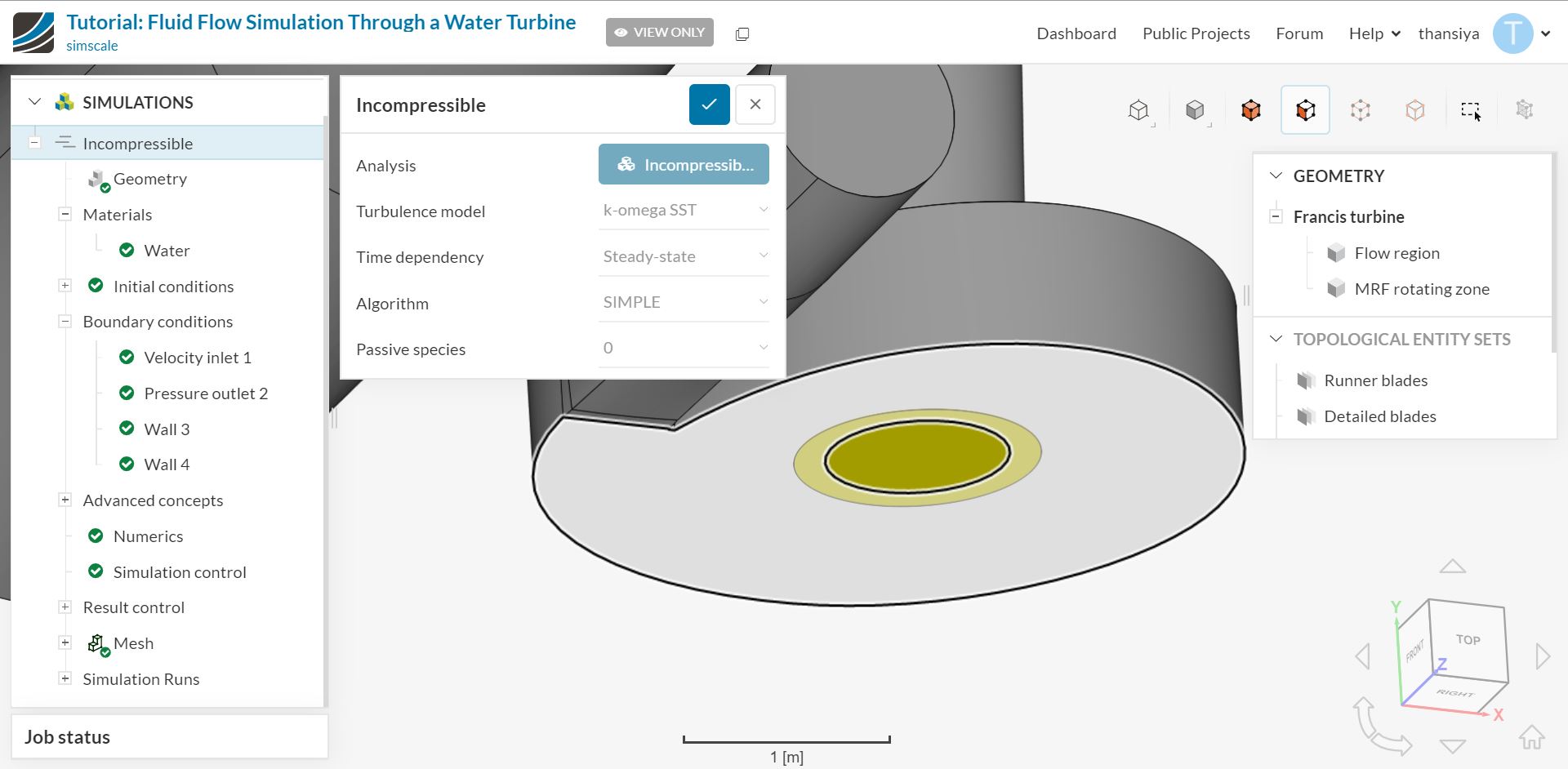
As i mentioned above, i have put the values of simulation setup by referring the journal.I watched some of the webinars of simscale and i tried the example of francis turbine. So that values or datas i didnt got; i have adjusted with the setup of this francis turbine setup. ( Fluid Flow Through a Water Turbine | Tutorial | SimScale )
one more thing that i would like to say is that, the blade cross section is of the shape of an airfoil ,named NACA0021 ( i browsed for NACA0020 ,but couldnt get it).The naca foil i have drawn is not by importing the coordinates from a csv file (as my pc showed error in doing that), so instead i traced the airfoil ( from image or canvas) and modelled using Fusion 360.
before importing the model ,i have combined different bodies of the turbine (blade,shaft,hub) into one body.
please do help…i dont have much time left for the submition
thanks a lot for the effort for reading this out.
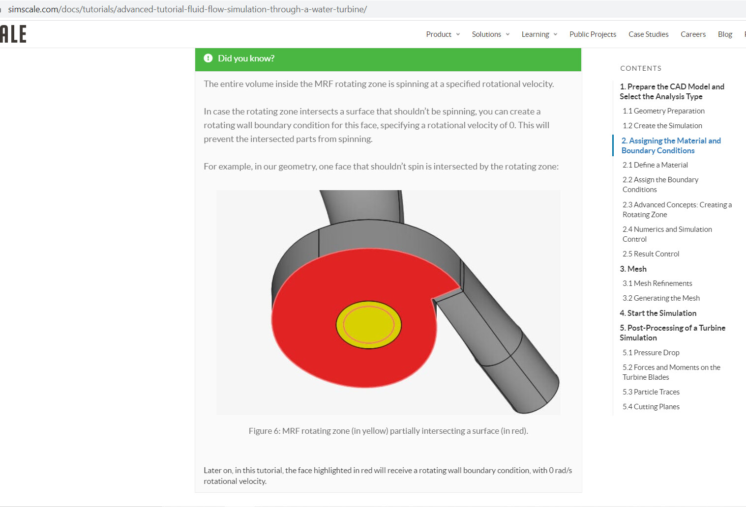
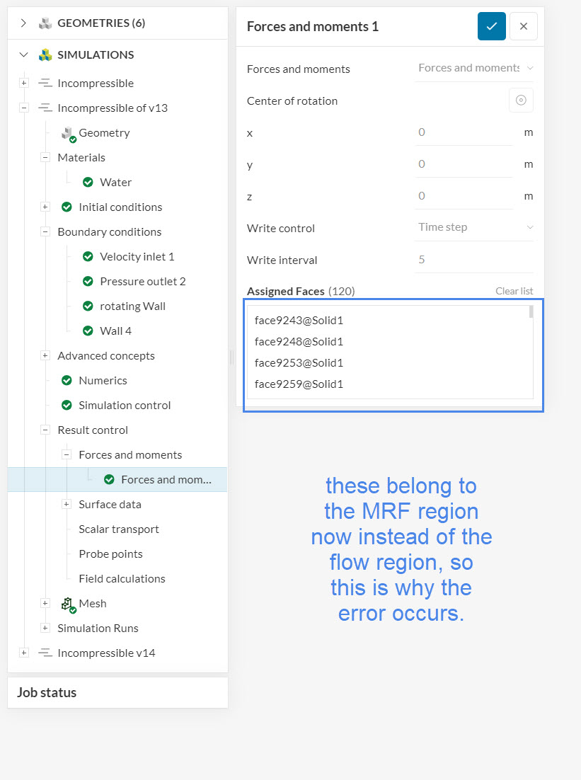
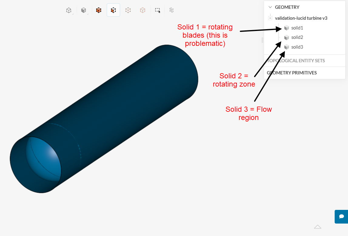
First, addressing the error that you are facing: a simulation with one rotating zone requires only two volumes: a flow region, and a volume representing the rotating zone. Any additional volume will cause a multi-region error, which is exactly what you have now.
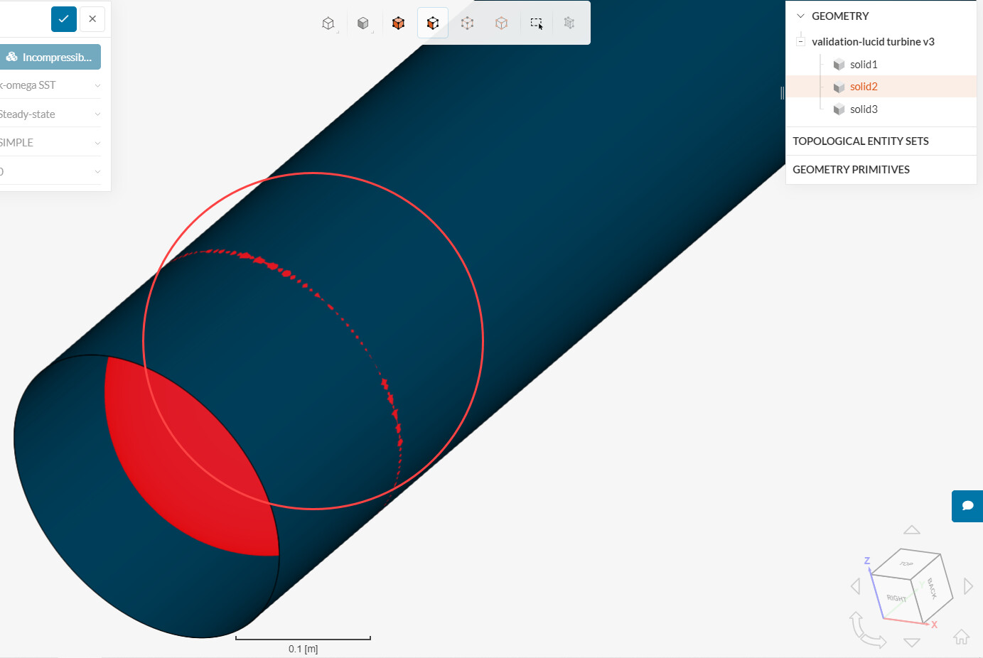
I would expect some poor mesh cells to generate there. Would it be possible to make the sphere a little larger, or perhaps use a cylinder for the rotating zone volume? The intention is to avoid small gaps between the rotating zone and the outer walls of the pipe.
If i remove rotating blades, the simulation setup will be left will the pipe and rotating region…
My goal is to analyze the turbine… So how can i remove that… Wont it be a different problem…
(may be my cad model iss too complex )
And about the size of rotating zone;
As it is a spherical rotor, i have seen in Journals that it will be having Spherical rotating region.
And if i change the shape of region, i would need to change the turbine design too…
They says that Spherical rotating region will be receiving more flow as compared to a cylindrical region (in case of pipe).
‘If i make the sphere larger…,’
Do U mean to convey, to make it little beyond the size of the pipe… (protruding out)…
Sorry this is the picture that i have got from reading. Will that be ok…
U can see what i am intending to do from the pictures of the journal, i have shared.
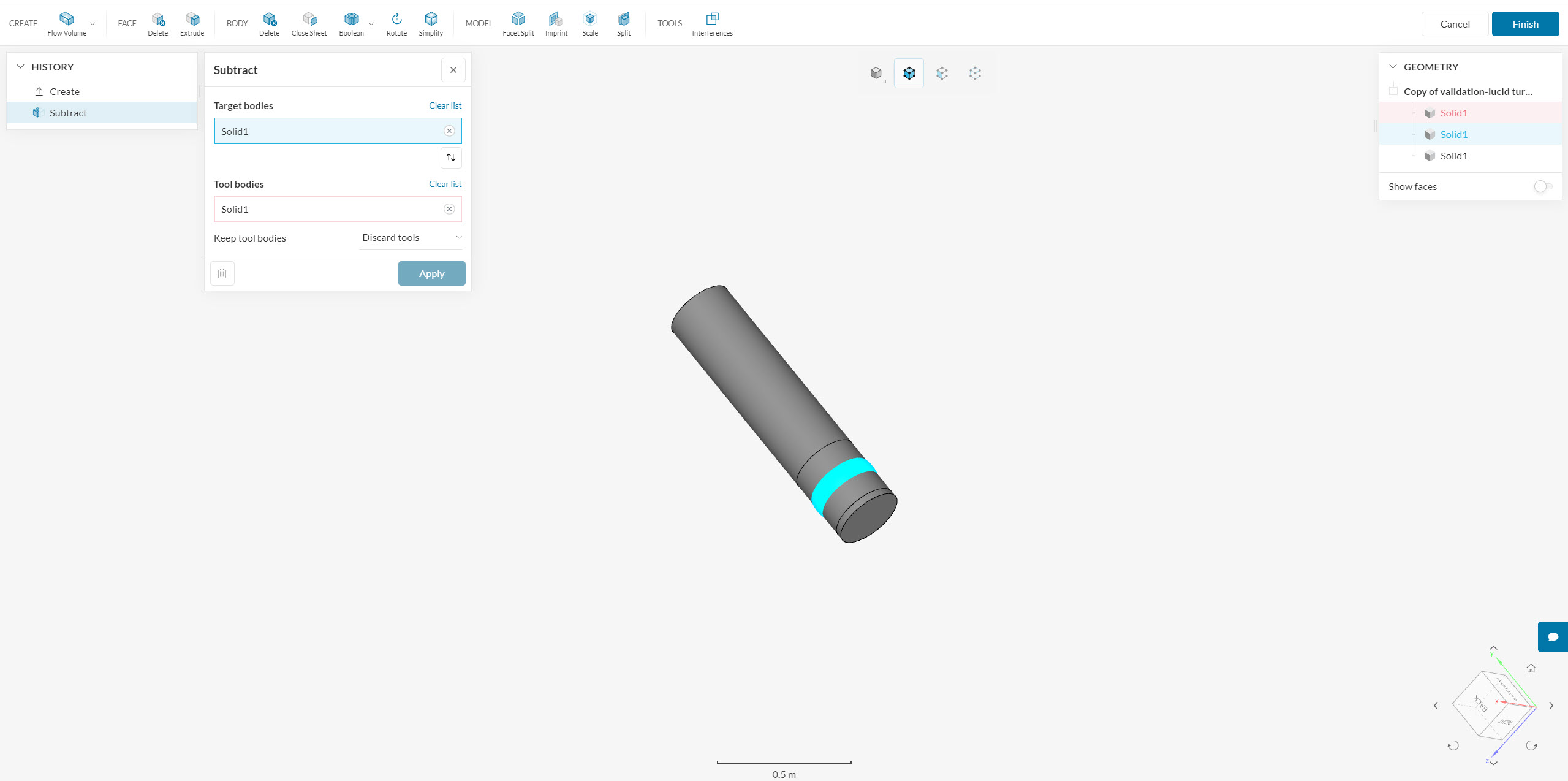
The idea with the blades is to capture the negative representation of their volume with this step:
And then, after having the negative representation of the blades, they should indeed be deleted from the CAD model (this is the correct workflow for this kind of analysis).
On your second pointer, sure, a sphere works. I’m just worried with the small gaps that we currently have between the sphere and the outer wall of the pipe (those can cause poor mesh quality/generate large meshes if you are not careful). In any case, making the radius of the sphere a little larger than it is right now would help in this sense.
 )
)