A Quick Question

Hello @BenLewis,

the pre stress seems to be easy.
How can I create a subdomain and what should be this domain? I guess only the bolt head or nut should be excluded from the pretensioned region.Does the stress remaining then constant over the time range?
However this method has its disadvantage when I will see the change in the bolt pretension when the construction deforms.

The Python script for ParaView would be brilliant :slight_smile: Keep me update regarding to this.

PS.: In the equation below the value will became less then zero befor time step three. Or do I misunderstand something?

Bests,
Csaba

Hi Csaba (@potyka_csaba),

I would recommend modelling the bolt and nut as one body.

To use initial conditions you need to be using the Static analysis - advanced analysis type. You also need to have nonlinear analysis set to true.

Under Model > Initial Conditions > Stress set Type to Subdomain-based and click Save.

Under Subdomains click +New.

Set the magnitude of pre-stress for the desired direction. Select a body to apply the pre-stress (in your case, the bolt).

Click save, that’s it.

Now, at time step zero the bolt will have the applied pre-stress. At the next time step the stress in the structure will equalise. The stress in the bolt will decrease as the forces balances with the surrounding structure. You will need to experiment with the applied preload to get the actual preload you require.

I recommend adding your dynamic loading at time step two so that the effects of bolt preload can clearly be seen in time step one.

Yes, you are right. The second load equation for Load1 should have been.

Load1: F1*((t-1)*(t>1)-2*(t-2)*(t>2))

Sorry about that. Good pick up.

Yes, you are right. The second equation for Load1 is only valid for three time steps. On the other hand the first form of the equation will work for any number of time steps. It’s just slightly more complicated because of the additional (t<3) term.

Regards, Ben

Hello @BenLewis,

could you check the model why the bolt pretension drops down after the second time step?

I tried everything you mentioned excepting the initial stress state.

Thanks in advance!
Csaba

Hi Csaba (@potyka_csaba),

I’ll have a look and get back to you in the next day or so.

Regards, Ben

Hi Csaba (@potyka_csaba),

I’ve taken a look at your simulation. Here are my comments.

You can find my copy of your project here https://www.simscale.com/projects/BenLewis/thermomechanics/

Loading Equations

Your loading equations are correct.

  • Bolt clearance: 0.0001*t*(t<=1)+0.0001*(t>1)
  • Internal pressure: 30000000*(((t-1)*(t>1))-((t-2)*(t>2)))
  • Fixed temperature: 293.15+(500*(t-2)*(t>2))

The equation for bolt clearance could also be expressed in one of the following ways:

  • 0.0001*t*((t<=1)+(t>1))
  • 0.0001*(t-(t-1)*(t>1))

All three forms are equivalent. I prefer the two alternative forms above because there is a clear distinction between the magnitude and the shape of the load (0.0001 is only used once). This just makes it less prone to mistakes when making adjustments.

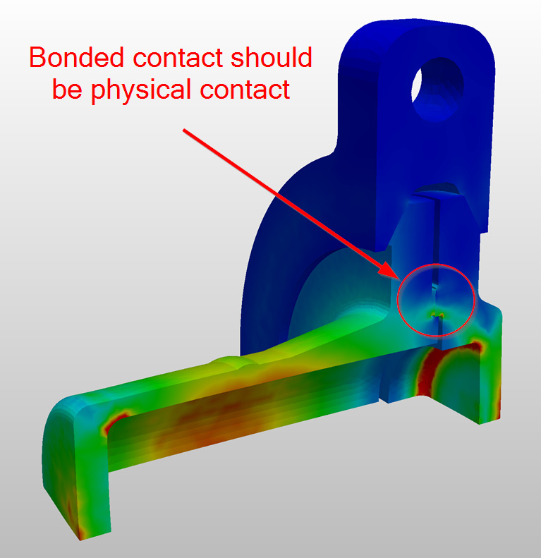
It looks to me that bolt tension drops off because of the mechanics of the structure. The seal ring, between the two flanges, is fixed on both sides with a bonded contact. This means that the two flanges cannot separate when the internal pressure is introduced. Instead, the flanges rotate about the seal ring taking pressure off the bolt. The fictitious clearance is maintained, it’s just that the internal pressure is so great that it completely unloads the bolt. Replacing the bonded contact with a physical contact allows the two flanges to separate.

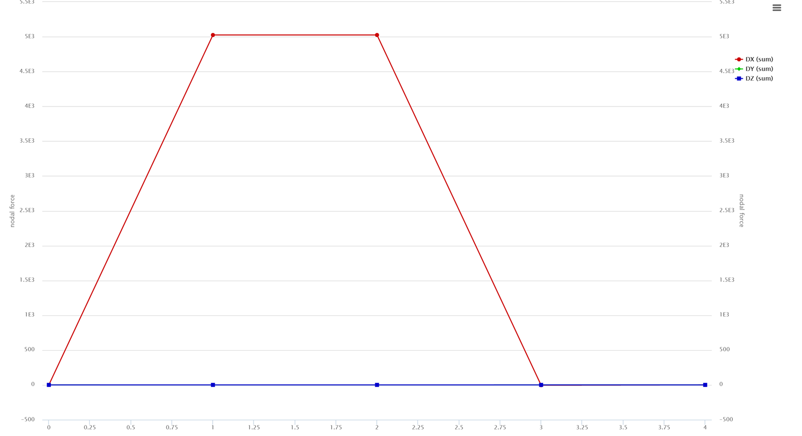
You can verify this by moving the the pressure and temperature loads one time step further along (see Simulation 2 - Run 1). Bolt load only drops off when the pressure load is introduced (time step 3).

Alternative approach

I’ve included an alternative approach to solve this problem (see Reactor03 FO Fine - Run 1). The main differences are:

  • Quarter model instead of full model
  • Overall finer mesh
  • Augmented Lagrange contacts instead of sliding or bonded contacts (most significant change)
  • Stress initial condition instead of fictitious clearance
  • Reduced magnitude of elastic support
  • Manual time stepping instead of automatic.

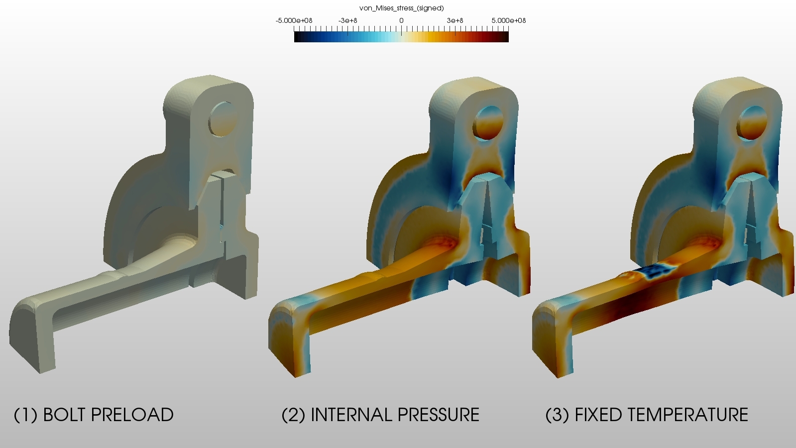
Here is a screen shot showing each time step.

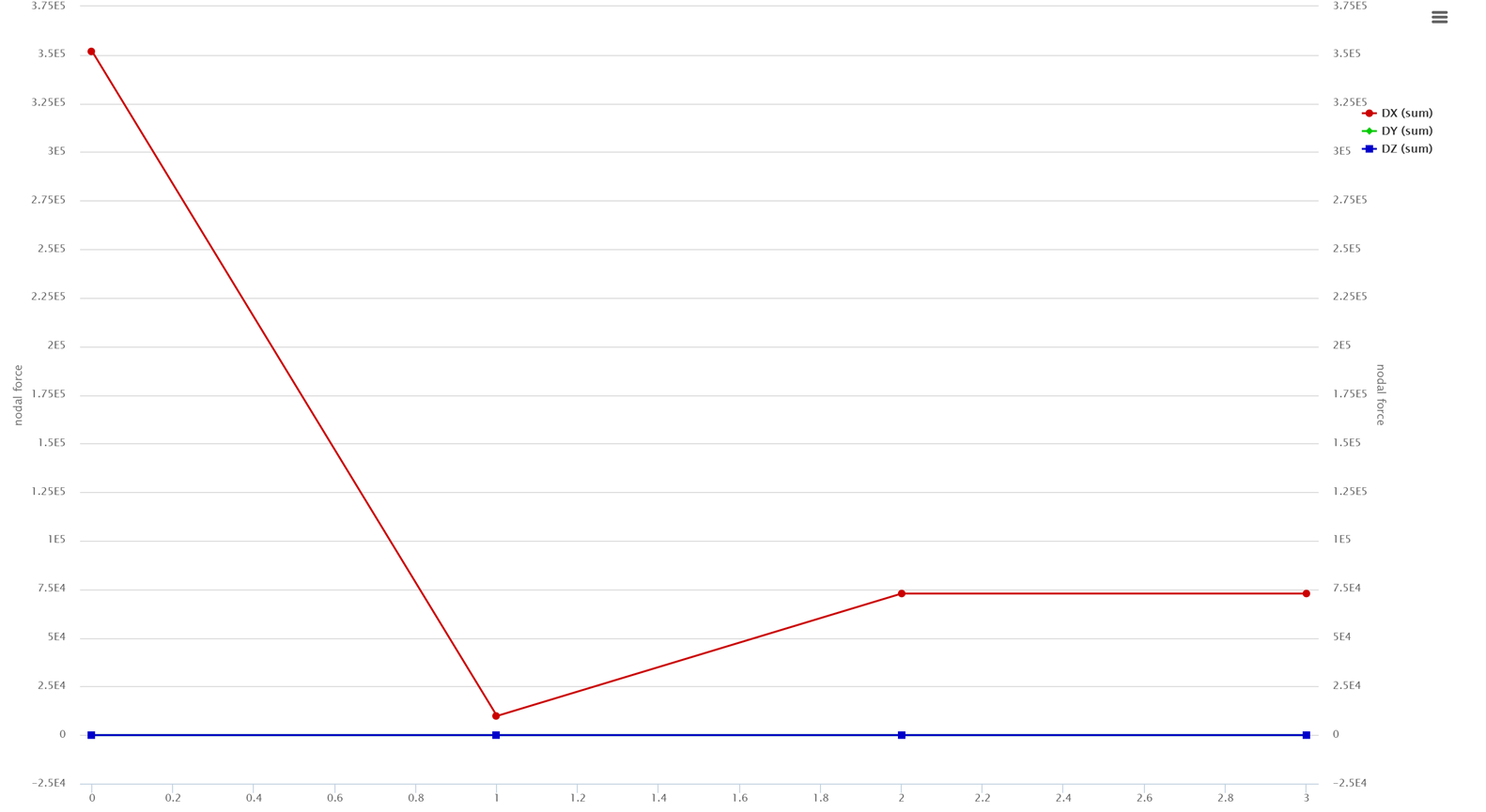
With the new constraints bolt force now increased with the introduction of internal pressure. This is to be expected because the bolt preload is not enough to overcome the large internal pressure (flanges separate).

Stress Difference Plots

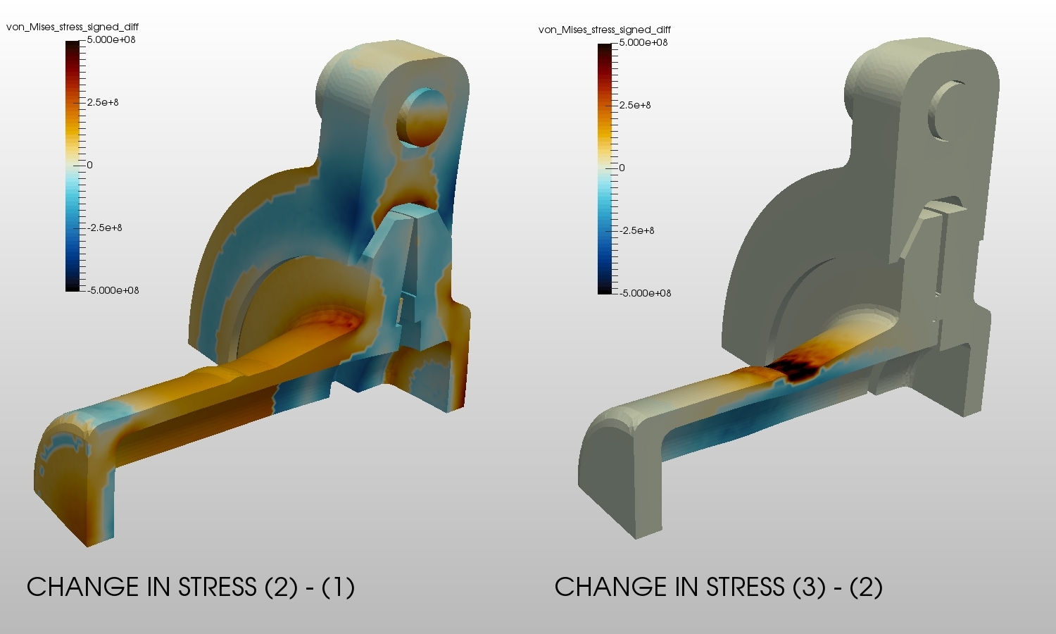
Here is a screen shot showing the change in stress from one time step to the next. This is useful for fatigue applications where the static stress does not contribute to the cyclic damage of the structure.

These plots were generated using a programmable filter in ParaView. I will post the code shortly.

Comments for SimScale

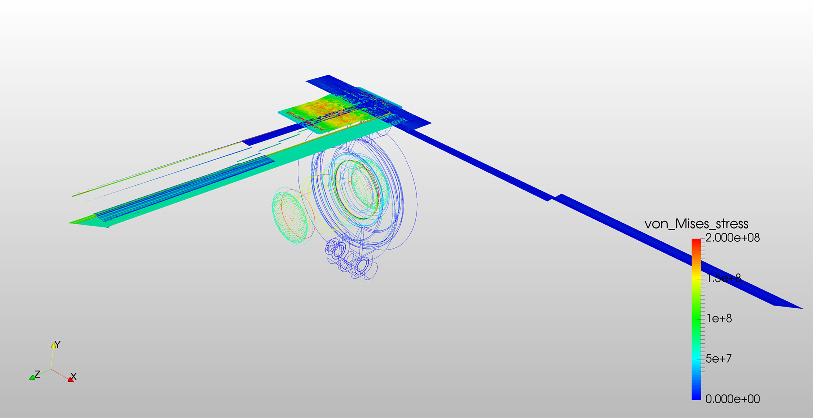
The results files for these simulations look odd when first opening in ParaView (see screen shot below). Using the Extract Block filter fixes the problem but this should not be necessary. Can somebody take a look at this please?

@afischer and @vdoelle, this model is very prone to the “selection bug”. You may want to take a look at this one.

Final Thoughts

This looks like a very interesting project. If I’ve misunderstood your application please let me know. I’m sure we can work out a suitable solution.

Regards, Ben

4 Likes

Hello @BenLewis!

It is great that you analyse this task so deeply! I will look in detail to the points you described. But first of all what kind of coloring did you used in ParaView? (I know it is a stupid question, but I like this colour setting :-)) .

Bests,
Csaba

Hi @potyka_csaba,

We’ve documented how to change the colors in ParaView in this post:

Cheers,
Anna

1 Like

Hi @potyka_csaba,

For the signed Von Mises stress field I typically use the color preset called “erdc_iceFire_H”. This works best if you scale the stress range equally in the positive and negative directions. This places zero stress in the center of the range which gets no color, compression is blue and tension is red.

Regards, Ben

Hey @potyka_csaba, adding to what @BenLewis mentioned here you can also change the ‘Number of Table Values’ in local Paraview in order to better see the change of stresses or whatever the quantity in more detail. This is mostly helpful in structural simulations and most of other commercial tools by default have a coarse contour. We are looking forward to have this feature available on online post-processor soon. Below are the example in case of temperature:

Refined table values (default):

Coarse table values (for better distribution understanding):

Hope this helps.

Best,
Ahmed

1 Like

Hi Csaba (@potyka_csaba),

I finally got around to creating a public project to demonstrate the use of a Paraview programmable filter for calculating stress differences.

You can view my public project here:

https://www.simscale.com/projects/BenLewis/custom_machines_-_engine_1/

Regards, Ben

2 Likes