I created 2 Load Conditions along with the Gravity Condition (is this to calculate the self weight). is there a way to view each condition result on it’s own and not a result of the sum of them all, without creating mesh and simulation for each individual case.
Just for practice and familiarization I think I will create another project with 2 copies of the same model and create 2 separate runs using the 2 Load cases.
Before I started using Simscale and still do for work I used S-Frame, in s-frame you can create as many load cases as required so I can view the results of different combinations.
hm - I’m not sure if this is what you’re looking for, but this would do the job:
You setup all load conditions within one simulation setup
Then you only apply (assign them to your model) the ones relevant to load scenario 1
Create a run from this setup, run it (“Run 1”)
Go back to the setup, now de-assign the conditions that are not part of scenario 2 and assign the new ones
Create a new from this setup, run it (“Run 2”)
(Repeat for each load case)
Ultimately this will lead to multiple runs that all stem from the same sim setup and reflect each individual load scenarios. Is that what you’re looking for?
In a word No.( Sorry i’m not being Blunt …lol) I was really hoping there was a way to view the result of each Load case separately without having to create Runs for each case, as this uses Core time on your servers and uses a lot of my computer time I am a complete beginner to using FEA and Simscale but enjoying every minute of it.
I originally asked this question in an email to Anna Flesnner, it was Anna who suggested I create a Post on the Forum
In my email, I followed on to say:
======================
Just for practice and familiarization I think I will create another
project with 2 copies of the same model and create 2 separate runs
using the 2 Load cases.
Before I started using Simscale and still do for work I used S-Frame, in s-frame you can
create as many load cases as required so I can view the results of
different combinations.
Instead of having to delete or re-assign loads and boundary conditions every time, have you given any thought to being able to suppress or unsuppress load and boundary conditions for a given run. That way you can set up all your loads, suppress the ones you don’t want, create your run, suppress/unsuppress the loads as needed and rerun. This saves the potentially tedious task of reassigning load and boundary conditions.
This seems a workaround, saving time inputting all the loads, but we still have to complete runs for each case still using a lot of computer time and extra load on Simscale Servers.
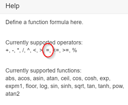
You can do what you are asking with functions. For example:
gravity: 9.81 (no function)
load1: 1000*((t=2)+(t=4))
load2: 2000*((t=3)+(t=4))
simulation interval: 4 s
time step length: 1 s
This will result in:
Time step1: gravity only
Time step2: gravity + load1
Time step3: gravity + load2
Time step4: gravity + load1 + load2
When you view the results you can look at the various load combinations by looking at each time step.
I like this approach because one simulation contains all the required load combinations. If you change one parameter (e.g. material stiffness) all load cases are updated.
If you are working on a public project I can help you set it up. Just share the link here.
Also, if the user enters a single equal sign instead of a double equal sign SimScale’s validation check should catch the error prior to starting the simulation.
Just for completeness, the correct equations to use in this situation are:
load1: 1000((t==1)+(t==3))* //where 1000 is the magnitude of the load present at time steps 1 and 3
load2: 2000((t==2)+(t==3))* //where 2000 is the magnitude of the load present at time steps 2 and 3
The Simulation Control definition should have the following settings:
Pseudo timestepping: Stepping list
simulation interval [s]: 3
time step length [s]: 1
Each time step will contain a different load combination:
Time step 0: Gravity only
Time step 1: Gravity + Load1
Time step 2: Gravity + Load2
Time step 3: Gravity + Load1 + Load2
I have tried to follow your tutorial, the run finished without an error, but when viewing it in the Post-Processor all the fields are greyed out and I can’t view the results, any ideas.
On re opening the project everything is working and all is fine, thanks a lot BenLewis for all your help, this is exactly what I was looking for, I will be using the Time Step on most projects, this should also cut down on Run Time.
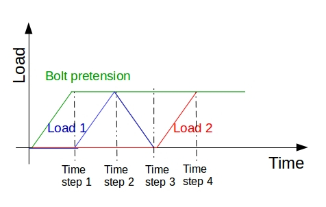
How ould you like set a load history which is shown below on the figure?
And would it be possible to combine the results by the following: 0.5*(Time step 3 - Time step 1)? For example if I want to see the “amplitude” of a fatigue loading.
Thanks in advance for the answer!
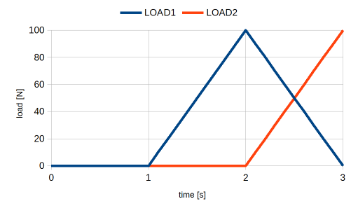
However, I’m not sure what the purpose of time step 3 is, as this is the same load case at time step 1. If time step 3 is not required you can save computation time by using the following equations.
This will result in a plot that contains the effect of load1 only.
However, this is only valid if the direction of stress is substantially the same in both cases. This is because stress is a vector quantity and the difference should be calculated vectorially.
In theory this should be pretty straight forward. It is just a case of subtracting one Cauchy stress tensor from the other. The resulting Cauchy stress tensor can then be used to calculate the “von Mises stress difference”. This is not something that I’ve done but it is something that I’m interested in doing. If I get the time I may have a go at this over the next few days otherwise @rszoeke might be able to help out here.
This is a great help, thanks a lot! You might have absolutely right; “Time step 3” is not that meaningful in my question! Nevertheless I am glad that you cached what I want to ask!
And yes you are right again; it is very important to manipulate only the Cauchy stress tensors (rotation of the mean stress directions can be tricky) when combine the stress results linearly. But this is the only way to extract the amplitude stress (von Mises for example) when you will check out the fatigue loading in the critical points of the assessed part. What to do with theese amplitude stress values is an other task but it is not directly related to FEM.
I will try out what you described above as soon as I will have time for it!
Let me know how you go with using functions. In the meantime I’ll have a go at writing a python script to plot the difference between two stress states.
is it possible, that in the equation for Load1 there is an unnecessary “t*”?
If I would like to use a bolt pretension applying fictitious clearance: 0.0001*(t-((t-1)*(t>1))), would it mean that the pretension remains constant (not zero) after the first time step?
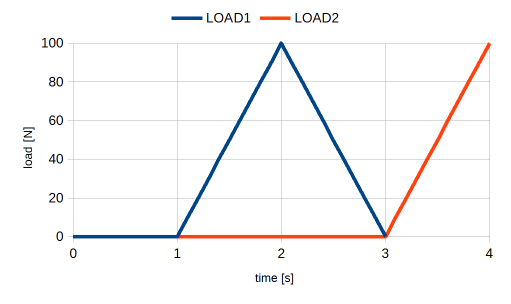
the equation for Load1 one will ramp the load up to a maximum between time steps one and two. It will then ramp the load back to zero between time steps two and three.
Your equation for bolt pretension will work as you expect. The clearance will ramp to a maximum between time steps zero and one. It will then remain at this value for all other times steps.
If your bolts are oriented in the direction of one of the global axes (X,Y, or Z) you may find it easier to apply pretension as an “initial condition”.
With regards to displaying the “stress difference” in ParaView I have written a programmable filter. It is working well. I just need to make an example public project to demonstrate its use. Stay tuned.