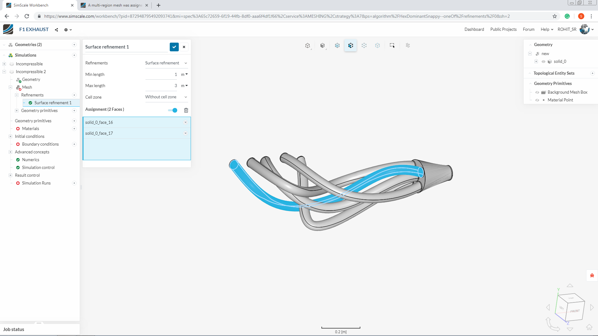
Looks to me like you’re using automatic Hex meshing which is identifying multiple separate bodies and creating different mesh volumes for each. If you manually create the mesh you can leave multi-volume unchecked. It may still create multiple volumes though since the bodies are completely separate.
Why not simulate each pipe individually? You’d have much smaller simulations instead of this huge one.
@ROHIT_SR: alas, you spent many meshing core-hours before failing with simulation. For INTERNAL simulation, you should have ONE internal volume. Your five pipes should have a communication zone or something like that. Of course, when you have that defined, you can have five inlets and five outlets. Otherwise it will not fly.
I suggest you do a very coarse mesh first, run a sim in a blink. If it works, remesh better and proceed with simulation.
@Retsam is absolutely correct regarding the communication thing. You can add a plenum type body at the outlet side of the exhaust pipes so that all the pipes become one integrated system.
This ‘plenum’ would need to be modeled in any case, all the way to the real inlet/outlet at that end with its associated and realistic inlet/outlet flow/pressure parameters… unless you really do have those parameters for the current 10 faces needed for in/outs…
I think adding the plenum at exhaust pipe outlet will make much sense as at exhaust pipe inlet, some will be having an inlet B.C while others will be behaving as a wall(some cylinder will be in exhaust stroke while some cylinders will have their exhaust valve closed, depending upon the firing order).
I was looking at this in a more general terms, not even knowing if intake or exhaust system (I did not look at project, just first post, likely exhaust tho)…
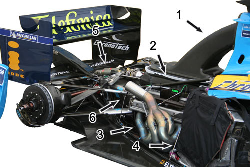
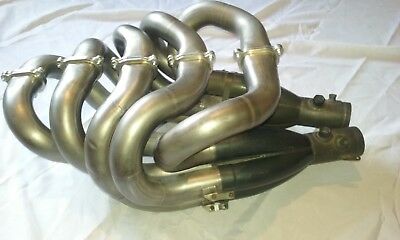
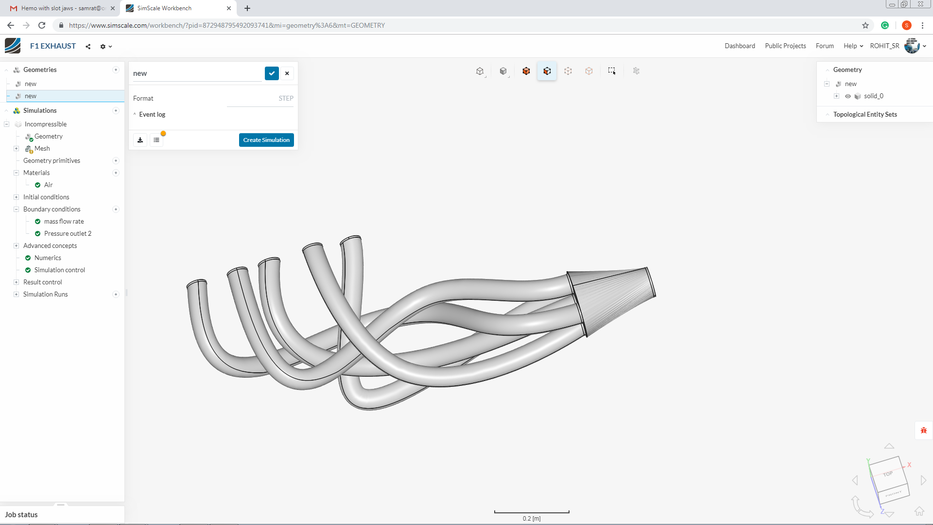
Where did you get the geometry from? Is it from a specific model because manifolds usually do not look that way and as Josh (@jhartung) mentioned, you could indeed simulate them separately if you keep them that way.
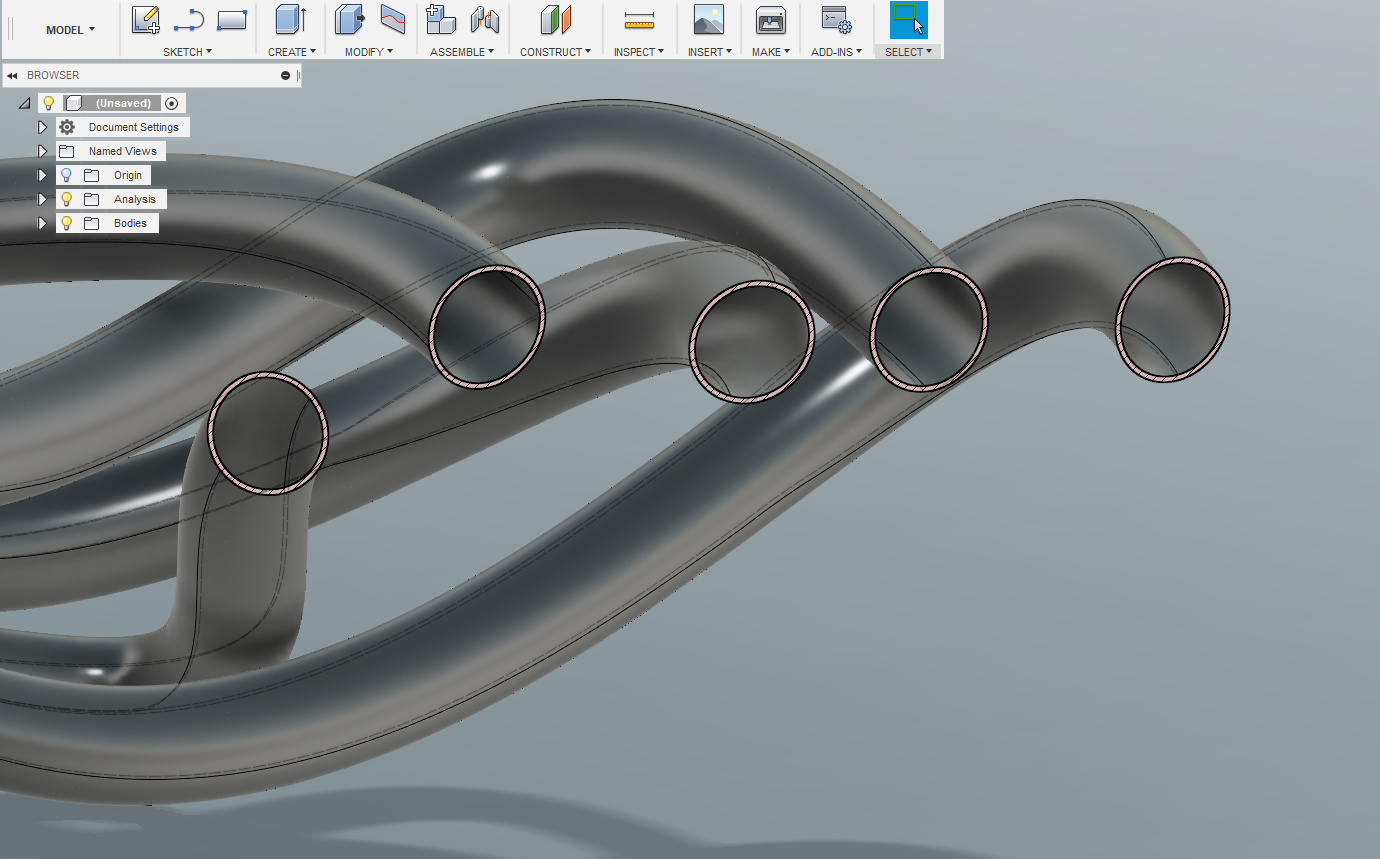
in my model, all bend are away from each other but in real life its look like very close to each other.
there is a huge mistake in the cad model? it does not look like f1 exhaust? @DaleKramer@anirudh2821998
if it is YES then I will change the cad model.
so for this simulation problem should I simulated each pipe separately? @jousefm
Do you have a CAD file of this exhaust or you created the CAD model by yourself?? Even if your purpose is to just practice simulating the exhaust manifold, you should take a genuine CAD(there are many models available on grabcad). But the issue is that you will not have any information/data to feed into the system while defining the B.C.'s.
No it is never done like that(unless it’s a single cylinder engine).
The end of your exhaust pipe do look somewhat similar to pagani huayra’s exhaust
If you don’t make your exhaust pipes into one integrated system, you will not be able to simulate this problem.
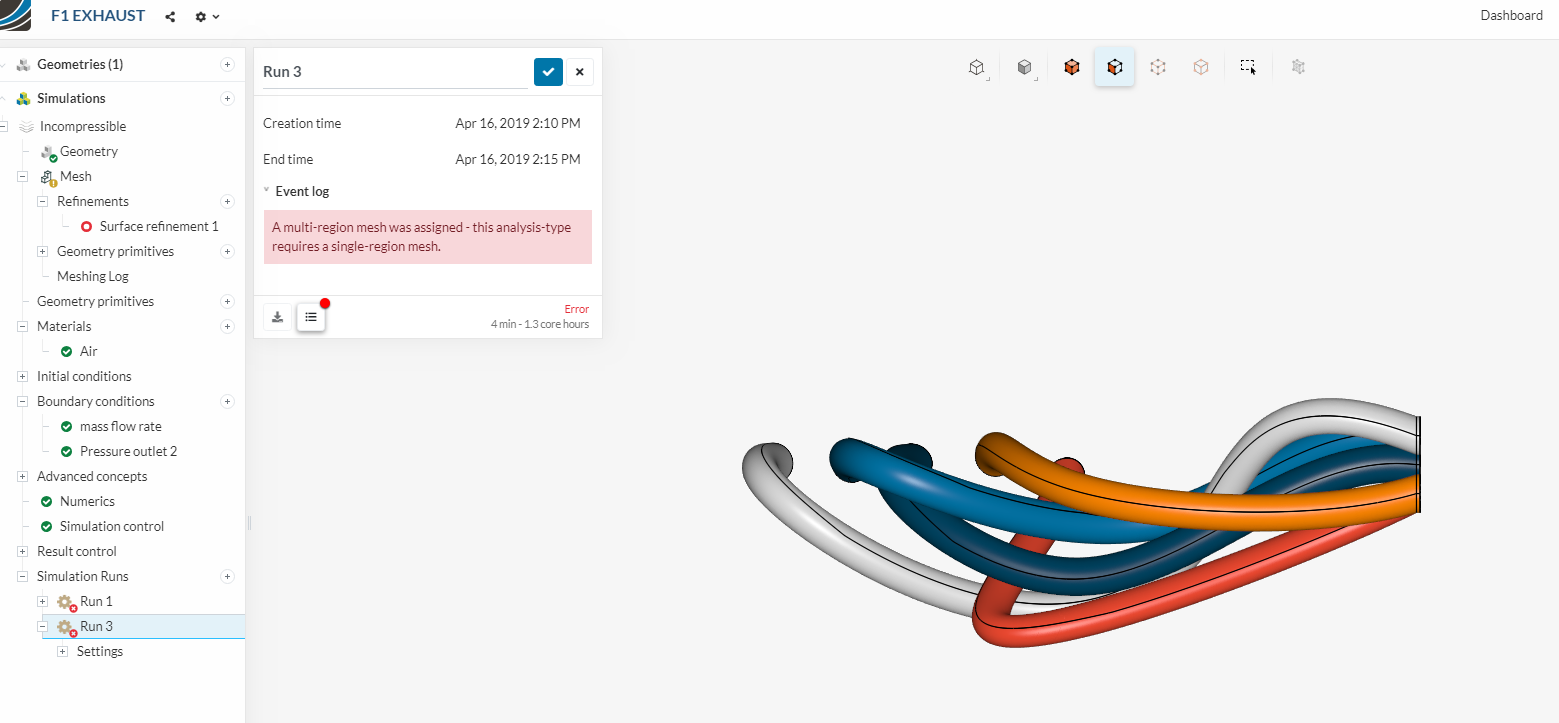
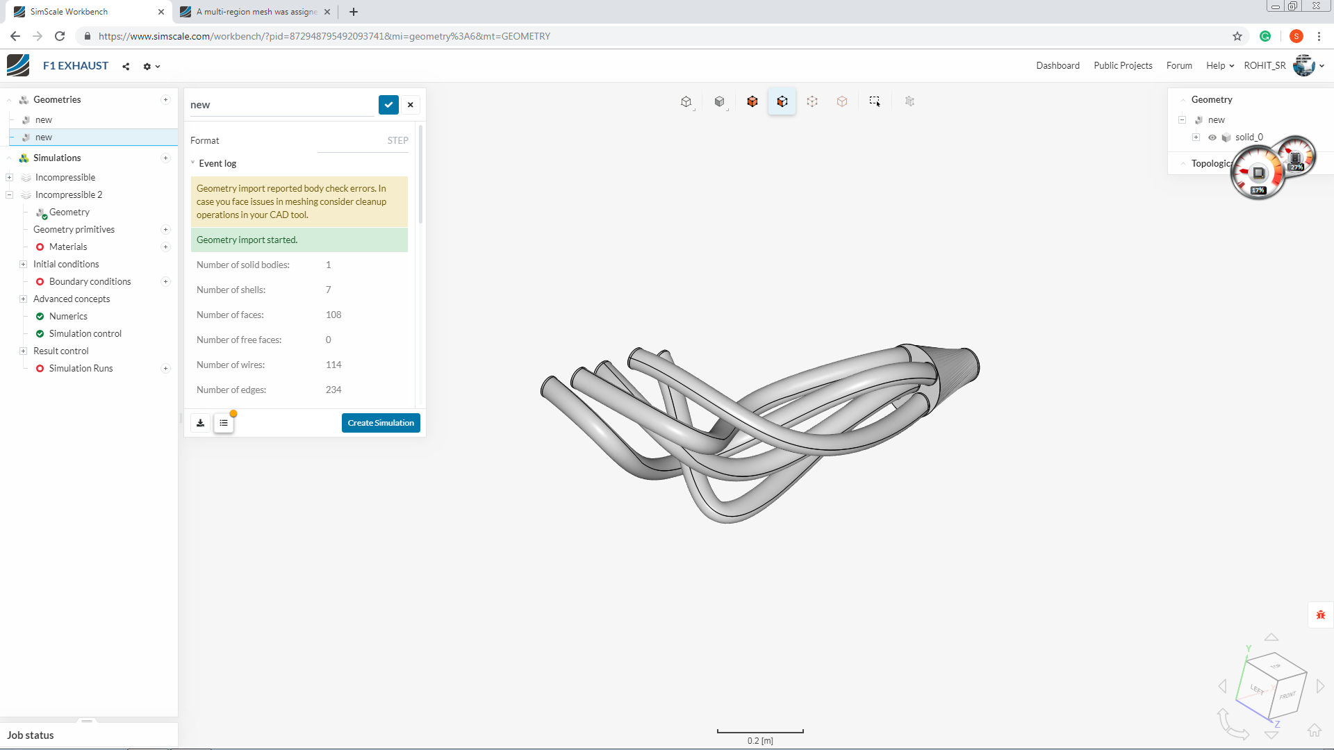
Looking or not looking like F1 exhaust is not a concern. The major concern are the multiple flow volume and difficulty in determining B.C’s (which I don’t know how Ricardo predicted just with a cad model).
Now that you have made it into one volume, there is no question of simulating one pipe at a time. The idea behind volume integration was to remove the meshing error and make the geometry ready for simulating your entire exhaust manifold.
How to simulate
In the above image I can see some warning with the geometry.so first check the issue with your geometry before you start the meshing process.
Assign inlet and wall B.C on the exhaust inlet side depending upon the firing order(some cyl will be in their exhaust stroke while for other cylinders the exhaust valve would be closed,meaning no air flow into the pipe)
this process is new for me I never tried this one in past. so help me.
can you explain step by step process for one pipe mesh? then I will do for all other
thank you,
Rohit.
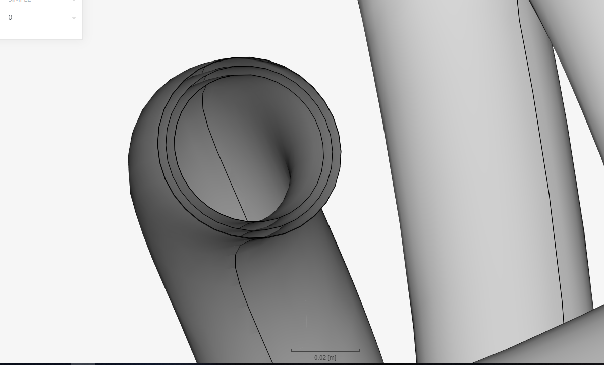
There is some issue in that too. Your geometry is multi layered. Try to work on your geometry first and then we will start working on the meshing and simulation part .
The issue of multilayered geometry is not yet solved. You should make a solid pipe(with dia= inner dia of the current pipe). The pipe thickness is not the flow domain rather it’s the inner hollow part of the pipe(stick to the basics ).