Surprisingly, I have found out that @bdelatti viewed my earlier project in February and successfully did the calculation by using 32 computing cores. So I copied my project from him :-), and have been doing some experiments that are little bit strange.
@bdelatti didn’t change anything in my simulation settings, just changed solver to MUMPS with 32 computing cores. I then added the 2nd pair of elastic supports to mimick the 2nd coil spring, tried replacing Force load by Remote Displacement condition to drive the linkage, but I still get extremely low stresses within the linkage.
The intended coil-spring stiffness is 44N/mm per coil. 1 spring is mimicked by 2 elastic supports that I placed on a circular support plates of 53mm diameter. Since the real-world coil spring is touching the support plate only by half of its perimeter, I multiplied the elastic support stiffness by 5.8 because the support area under coil-end is 6x smaller than entire support plate.
22N/mm per coil-end multiplied by 6 is cca 130.000N/m.
I have to take into account the force that has been accumulated in the spring before the spring reached its maximum load and linkage reached its final point. The “preload” of the spring. So, 22N/mm per coil-end, multiplied by 57mm of spring stroke, multiplied by 5.8 is cca. 7.400.000N/m. I put this number into spring stiffness field of each of the four elastic supports.
And the result of calculated Von Mises stress is the same with or without the preload, Which is very strange, because I have put the fixed support at top most part of the assembly, so the input force of 1.800N with high spring loads must be acting against this fixed support. There must be much more stress in assembly.
When I simulate stress analysis of the top most part with forces and moments that Autodesk Inventor calculated, the stress is absolutely different to what I have “simulated” using elastic supports in assembly.
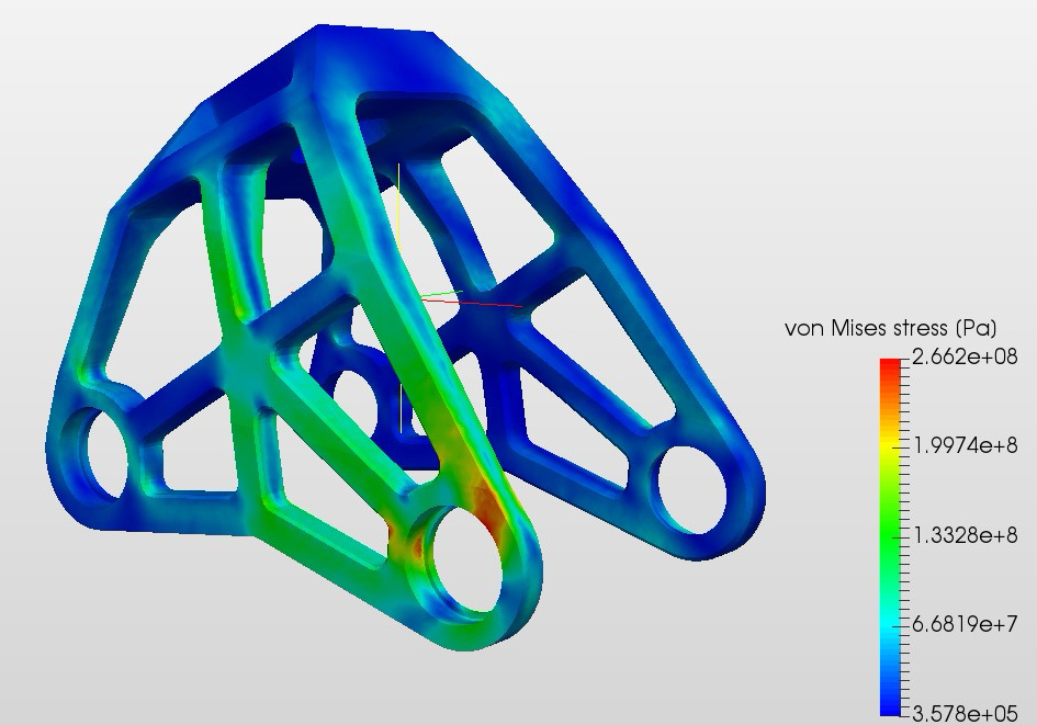
Sole part simulation:
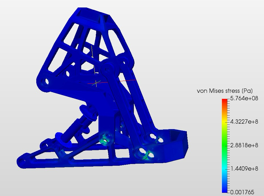
Assembly simulation with all loads I could think of: